


The Engineering of Resilience: Understanding Thermal Throttling in Portable Inflators
TL;DR for Buyers
Thermal throttling is what keeps a portable inflator from cooking its own motor in hot, high-pressure jobs. Good inflators:
- Use motor-mounted temperature sensors (NTC thermistors), not just battery protection.
- Slow down in steps (audible RPM drop) instead of hard-shutting off under load.
- Are honest about duty cycle and cooldown time.
- Manage very hot outlet air (theoretical exhaust can exceed 200 °C in extreme scenarios) so that heat doesn’t soak into the motor and battery.
If you often inflate in hot weather or with large tires (RV, off-road, trailers), pick a unit with clear thermal protection design, not just high PSI marketing.
Quick Check List: How to Spot a Better-Protected Inflator
- Has motor-specific protection: Product page/manual mentions an NTC sensor on the motor or “motor temperature monitoring,” not just battery BMS.
- Duty cycle is clearly stated: e.g., “up to 40 min continuous at 30 PSI, then automatic cooldown” instead of vague “long-lasting.”
- Audible throttling: Under heavy load, you can hear a smooth, stepped drop in speed, not a sudden cutout.
- Thoughtful venting: Air inlets/outlets are placed near the motor and commutator area, not randomly on the shell.
- Safety language, not only PSI bragging: Specs talk about temperature control, protection, and compliance (e.g., IEC/EN safety standards), not just “150 PSI!”
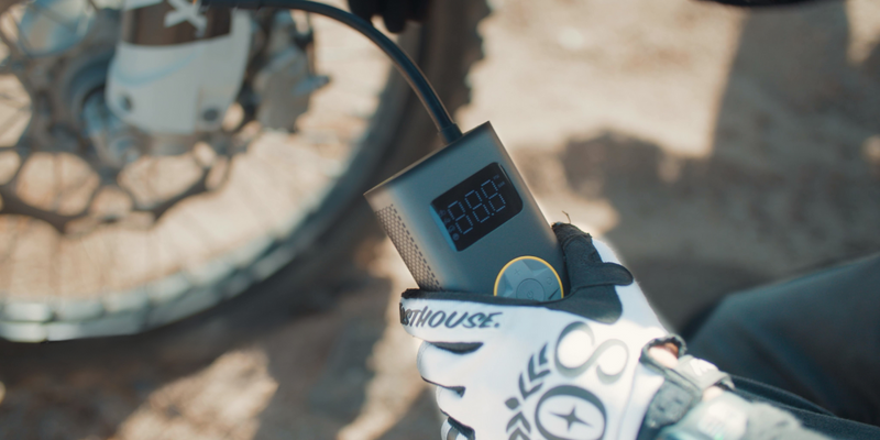
For automotive enthusiasts and DIY users, the reliability of emergency gear is measured in moments of stress. When a tire loses pressure on a remote desert trail or a high-pressure RV tire requires a top-off in mid-summer heat, the internal components of a portable inflator face extreme thermal loads. In these high-consequence scenarios, the difference between a successful inflation and a catastrophic motor failure often comes down to a sophisticated engineering control known as thermal throttling.
Thermal throttling is the proactive reduction of a device's performance to prevent heat-related damage. In the context of battery-powered compressors, this mechanism protects the motor windings and the lithium-ion power cells from reaching temperatures that compromise their structural integrity. By examining the mechanics of heat generation and the sensor-driven logic that mitigates it, users can better understand how modern engineering helps ensure long-term tool safety.
The Physics of Heat Generation in High-Pressure Systems
Portable inflators generate heat through two primary mechanisms: electrical resistance and adiabatic compression. As the motor draws current from the battery to drive the piston, electrical energy is converted into mechanical work. However, no system is perfectly efficient. A portion of this energy is lost as heat due to the resistance in the copper motor windings and the friction of moving parts.
The more significant heat source in high-pressure applications is adiabatic heating. According to the first law of thermodynamics, when air is compressed rapidly, its temperature rises significantly because the work done on the gas increases its internal energy.
Logic Summary: The qualitative analysis of thermal loads assumes that as pressure increases, the work required per stroke rises, leading to a non-linear increase in heat generation. This is based on standard gas laws where, in an idealized closed system, temperature tends to rise as pressure rises.
In a typical automotive high-pressure scenario, the air exiting the cylinder can reach well over 150 °C, and under extreme conditions it can exceed 200 °C. These are order-of-magnitude figures based on ideal-gas, adiabatic-compression estimates and not universal limits for all inflators.
Without a robust thermal management system, this very hot air can soak into the motor housing and surrounding electronics, potentially leading to conditions approaching thermal runaway—a state where the device generates heat faster than it can dissipate it.

The Anatomy of Protection: NTC Thermistors and Smart Sensors
To manage these thermal loads, high-quality inflators utilize NTC (Negative Temperature Coefficient) thermistors. These are specialized resistors whose resistance decreases as temperature increases. By placing an NTC thermistor in direct contact with the motor housing, a microcontroller (MCU) can monitor real-time thermal data.
Contrary to the misconception that such protection is prohibitively expensive, the core components for basic thermal monitoring are remarkably accessible. A standard 10K NTC thermistor often costs well under $1, and a dedicated 8-bit microcontroller capable of processing this data and modulating power via a MOSFET is typically also a low-cost component (pricing varies by supplier and volume).
Evidence Type: These cost observations are based on common electronic component distributor listings, not on a single brand’s bill of materials.
However, the efficacy of this system depends heavily on the quality of the thermal interface. Practitioners in the field often point out that the thermal paste or pad applied between the motor housing and the sensor is a critical failure point in lower-tier units. Poor application leads to “laggy” temperature readings. If the sensor detects a safe temperature while the motor windings are actually overheating, the throttling response will be delayed, increasing the risk of permanent insulation damage.
Why Motor Protection Differs from Battery Management
A common assumption among risk-averse buyers is that the Battery Management System (BMS) provides sufficient protection for the entire device. While the BMS does monitor the lithium-ion cells—typically triggering a shutdown if they exceed roughly 55–65 °C (based on manufacturer guidance and battery-technology primers)—the motor windings operate under much tighter thermal margins and heat up significantly faster.
Motor windings are protected by a thin layer of polymer insulation. A commonly cited engineering rule of thumb is that the functional life of motor insulation approximately halves for every 10 °C rise above its rated temperature. This “10-degree rule” is a heuristic summarized in motor-industry literature and training materials, not a hard law of physics.
For example, a motor rated for Class A (105 °C) that operates noticeably above this rating due to a lack of localized sensors can experience sharply accelerated insulation aging and a substantial reduction in expected life. The exact percentage will depend on the insulation system and operating history.
Because the motor's thermal mass is much smaller than the battery pack's, it can reach critical temperatures while the batteries remain relatively cool. Therefore, a dedicated sensor on the motor housing is essential for a truly redundant safety architecture, as emphasized in industry whitepapers on “essential gear” design (these are typically manufacturer or industry association perspectives, not independent standards).
The "Stepped Reduction" Heuristic: Safety vs. Abrupt Failure
The most sophisticated thermal throttling systems do not simply cut power when a limit is reached. An abrupt power cut under high pressure can cause a pressure spike in the hose line, potentially stressing internal valves or the tire stem.
Instead, many reliable designs utilize a “stepped reduction” curve. As the internal motor temperature approaches a defined engineering threshold, the MCU reduces the motor's RPM. This is often audible to the user as a smooth, downward shift in pitch.
Design Note (Heuristic, not a standard): In practice, some engineering teams target a throttling region where, as the motor casing temperature approaches roughly 80–90 °C, the controller gradually reduces output to around 50–60% of peak performance. This kind of curve:
- Lowers the rate of heat generation from electrical resistance.
- Preserves enough airflow over the motor (if the unit has an internal fan) to facilitate cooling without stopping the job entirely.
These values are rules of thumb for controller tuning, not mandated regulatory limits. Different products can legitimately choose different setpoints.
Scenario Modeling: The Desert RV Thermal Stress Test
To illustrate why thermal throttling matters, consider a high-stakes, worst-case usage pattern. This is a scenario model, not a lab-certified test protocol, and it is intended to show how quickly heat can build up if you push an inflator hard in extreme conditions.
The Scenario (Illustrative):
An RV owner needs to inflate 6 tires (4 main, 2 spares) from 15 PSI to 65 PSI in extreme ambient heat (45°C / 113°F).
| Parameter | Value | Unit | Rationale |
|---|---|---|---|
| Ambient Temperature | 45 | °C | Extreme desert summer conditions |
| Total Tires | 6 | Count | Standard RV + spares configuration |
| Start/End Pressure | 15 / 65 | PSI | Significant under-inflation to a typical RV spec range |
| Estimated Runtime | 90 | Minutes | Approximate continuous run time based on large light-truck tire volume |
| Theoretical Exit Air Temp (model) | ~240–250 | °C | Ideal-gas, adiabatic estimate under simplifying assumptions |
Methodology Note (Illustrative Adiabatic Estimate):
This temperature estimate uses a simplified adiabatic-compression model for air:[ T₂ = T₁ \times \left(\frac{P₂}{P₁}\right)^{(k-1)/k} ]
where:
- T₁: inlet air temperature (in Kelvin). Here we assume T₁ ≈ 318 K (45 °C ambient).
- P₁: initial absolute pressure in the cylinder.
- P₂: final absolute pressure in the cylinder.
- k: adiabatic index for air (≈ 1.4).
In real compressors, the instantaneous cylinder pressure ratio at the piston face during each stroke can be significantly higher than the tire’s gauge pressure ratio (15 → 65 PSI). If we assume an effective compression ratio on the order of 6:1–7:1 inside the cylinder for the high-pressure part of the stroke, the ideal-gas equation yields peak gas temperatures on the order of 240–250 °C at the outlet:
- Example: T₂ ≈ 318 K × (6)^{(1.4−1)/1.4} ≈ 318 K × 1.7–1.8 ≈ 540–570 K (≈ 265–295 °C).
- Factoring in some heat loss and non-ideal behavior, a back-of-envelope range around ~240–250 °C is a reasonable illustrative figure for peak exhaust gas temperature in this kind of scenario.
Important Boundaries:
- This is a theoretical, order-of-magnitude model, not a measured value for any specific product.
- Actual temperatures will vary with compressor design, duty cycle, cooling, and hose length.
- This estimate is not a regulatory limit or universal safety threshold.
Analysis Findings (Scenario-Level, Not a Spec):
- In this kind of extended, high-temperature, multi-tire job, a compact inflator will almost certainly need to throttle or pause to protect itself.
- The ~90 minutes of continuous runtime in the table is a rough, idealized number used to illustrate that this workload is heavier than the continuous duty cycle of many portable units (often in the few tens of minutes range for high load).
- Without throttling or cooldown, the modeled very hot outlet air would accelerate motor insulation aging and increase stress on nearby components.
In practice, for a user doing this job with a well-protected inflator, the total wall-clock time might extend to around two hours once you account for enforced cooldowns and stepped power reductions. The trade-off is that the tool remains usable for future emergencies instead of becoming a one-time-use device.
Compliance and Regulatory Standards
The integration of functional thermal protection isn't just good engineering; it increasingly aligns with regulatory expectations.
Under the EU General Product Safety Regulation (EU) 2023/988, manufacturers are obligated to ensure that products do not pose a risk to consumers under "reasonably foreseeable conditions of use." This includes foreseeable misuse and harsh environments. For inflators, that means addressing hazards such as burns from overheated casings or fire risk from internal component failure.
Furthermore, adherence to standards such as IEC 60335-1 (Safety of household and similar electrical appliances) provides a framework for testing the thermal limits of motors and other components. These standards typically include "abnormal operation" tests, where a device is pushed beyond normal use to confirm that, even in fault or overload conditions, it remains within defined safety margins.
Evidence Type: Regulations (like EU 2023/988) and IEC/EN standards are formal, third-party requirements. They set safety expectations but do not dictate specific internal throttling curves or exact temperature thresholds for every inflator.
Identifying Quality: What to Look For
For the risk-averse buyer, identifying a robust thermal management system involves looking past the peak PSI numbers and marketing slogans.
Key external cues you can check before buying or during first use:
- Venting Placement: Higher-quality units often feature intake and exhaust venting positioned to sweep air past the motor and commutator. This is where brush arcing and copper losses generate intense localized heat, and direct airflow is essential for cooling.
- Duty Cycle Transparency: Reliable brands clearly state their duty cycle (for example, "up to 40 minutes continuous at 30 PSI, then automatic cooldown") and explain that the device will pause or slow down to cool itself.
- Audible Feedback: During use, listen for the "stepped reduction" under heavy load. A device that maintains a constant, high-pitched whine until it suddenly smells of ozone or shuts off completely likely relies on a crude over-temperature cutoff rather than a tuned throttling curve.
- Thermal Behavior in First Test: On a controlled first use (e.g., topping off your own tires at home), note whether the casing becomes uncomfortably hot to the touch and whether the unit provides any warning or cooldown behavior. Rapid, repeated overheating without feedback is a red flag.
- Documentation and Safety Section: Check the manual or product page for mention of temperature sensors, over-temperature protection, standards compliance, and operating limits. Vague language like "premium motor" without any safety detail is less reassuring.
Summary of Thermal Safety Engineering
Thermal throttling is a critical engineering control that acts as a failsafe against user error and environmental extremes. By proactively reducing performance and, when necessary, enforcing cooldowns, smart sensors help keep the motor within its safe thermal envelope and reduce stress on the battery and electronics.
For automotive preparedness—where a tool may sit unused for months and then be expected to perform perfectly in a high-stress moment—these hidden thermal protections often matter more than the headline PSI rating. Understanding what to look for in venting, duty cycle transparency, audible behavior, and documentation can help you choose an inflator that is built not just to work, but to keep working safely.
Disclaimer: This article is for informational purposes only and does not constitute professional engineering or safety advice. Always refer to your specific device's user manual and local regulations for operating limits and safety warnings.
Sources
* EU General Product Safety Regulation (EU) 2023/988 – *formal consumer safety regulation*. * Dreisilker Electric Motors: "How Extreme Heat Impacts Electric Motors" – *industry educational content summarizing insulation life heuristics*. * Mouser Electronics: NTC Thermistor specifications – *component datasheets from an electronic distributor*. * Motor repair and training resources on thermistors for electric motors – *industry practice references*. * Manufacturer and industry whitepapers on “essential gear” design – *non-independent, manufacturer/association perspectives on redundancy and safety architecture*.Continue reading
 Troubleshooting Temperature Warning Lights on Your Jump Pack
A guide to troubleshooting temperature warning lights on portable jump starters. Learn about BMS safety protocols and how...
Troubleshooting Temperature Warning Lights on Your Jump Pack
A guide to troubleshooting temperature warning lights on portable jump starters. Learn about BMS safety protocols and how...
 Comparing Hard-Shell vs. Soft-Case Insulation for Batteries
Covers the 2,650A power gap, cooling paradox, thermal bridging, and a 20-minute pre-warming protocol for extreme cold operation.
Comparing Hard-Shell vs. Soft-Case Insulation for Batteries
Covers the 2,650A power gap, cooling paradox, thermal bridging, and a 20-minute pre-warming protocol for extreme cold operation.

Leave a comment
This site is protected by hCaptcha and the hCaptcha Privacy Policy and Terms of Service apply.