


The Zero-Gap Standard: Evaluating Build Quality in Shells
When you pick up a high-performance tool, your first impression isn't formed by the spec sheet; it is formed by the palm of your hand. For the detail-oriented DIYer or the professional technician, that initial tactile feedback—the "handshake" of the tool—reveals more about internal engineering than any marketing brochure. We often hear the term "Zero-Gap" used to describe premium electronics and hardware, but in the world of precision manufacturing, this term represents an aspirational target rather than a physical absolute.
Understanding how to evaluate the exterior shell of a tool is a critical skill for any prosumer. It allows you to peer through the plastic and metal to see the quality of the molds, the robustness of the internal chassis, and the maturity of the manufacturing process. As we detailed in The 2026 Modern Essential Gear Industry Report: Engineering Trust in a Cordless World, true reliability is a function of "credibility math"—the systematic engineering of every seam and joint to withstand real-world stress.
The Engineering Reality: Why "Zero" is a Misnomer
In professional circles, we recognize that a literal "zero gap" is physically impossible and, from an engineering standpoint, undesirable. Materials expand and contract with temperature changes. If a shell had zero clearance, the slightest thermal expansion would cause the housing to warp or crack.
Instead of chasing a literal zero, high-quality manufacturers adhere to strict tolerance standards. According to ISO 2768-1: General tolerances, linear dimensions for small parts (0–6mm) in the "Fine" class allow for a tolerance of ±0.1mm. When you see a "Zero-Gap" shell, what you are actually seeing is a manufacturer successfully holding tolerances well within that fine window across complex, curved surfaces.
Logic Summary: Our evaluation of build quality assumes that "Zero-Gap" refers to visual consistency and alignment within ISO 2768-1 "Fine" tolerances (±0.1mm), which indicates high-maturity mold design and assembly control.
Visual Auditing: Spotting the Tell-Tale Signs of Quality
To the untrained eye, a shell is just a container. To a pro, it is a map of the factory's capabilities. Here is how we audit the build quality of a tool shell before we ever turn it on.
1. Seam Consistency on Curved Surfaces
The hardest part of injection molding is controlling the flow of molten plastic around corners. In rushed development cycles, you will often see inconsistent gaps—wider at the apex of a curve and tighter on the flats. This happens because cooling rates vary across different geometries, causing the plastic to shrink unevenly. A tool that maintains a perfectly uniform 0.1mm seam around a 90-degree corner demonstrates superior mold flow analysis and thermal management during production.
2. Transition Zones and Material Bonding
Modern tools frequently use "overmolding"—the process of bonding a soft rubber grip to a hard plastic housing. We pay close attention to the transition zones here. If you see peeling, gapping, or "flash" (excess material) where the rubber meets the plastic, it is a leading indicator of a bonding process failure. In our workshop observations, these gaps are the first places where oils and solvents will penetrate, eventually causing the grip to delaminate entirely.
For example, when inspecting a high-performance device like the Fanttik Slim V8 Apex Car Vacuum RobustClean®, we look for a seamless transition between the aerodynamic nozzle and the main motor housing. Any misalignment here wouldn't just be an aesthetic flaw; it would create turbulence that reduces the 19,000PA suction efficiency.

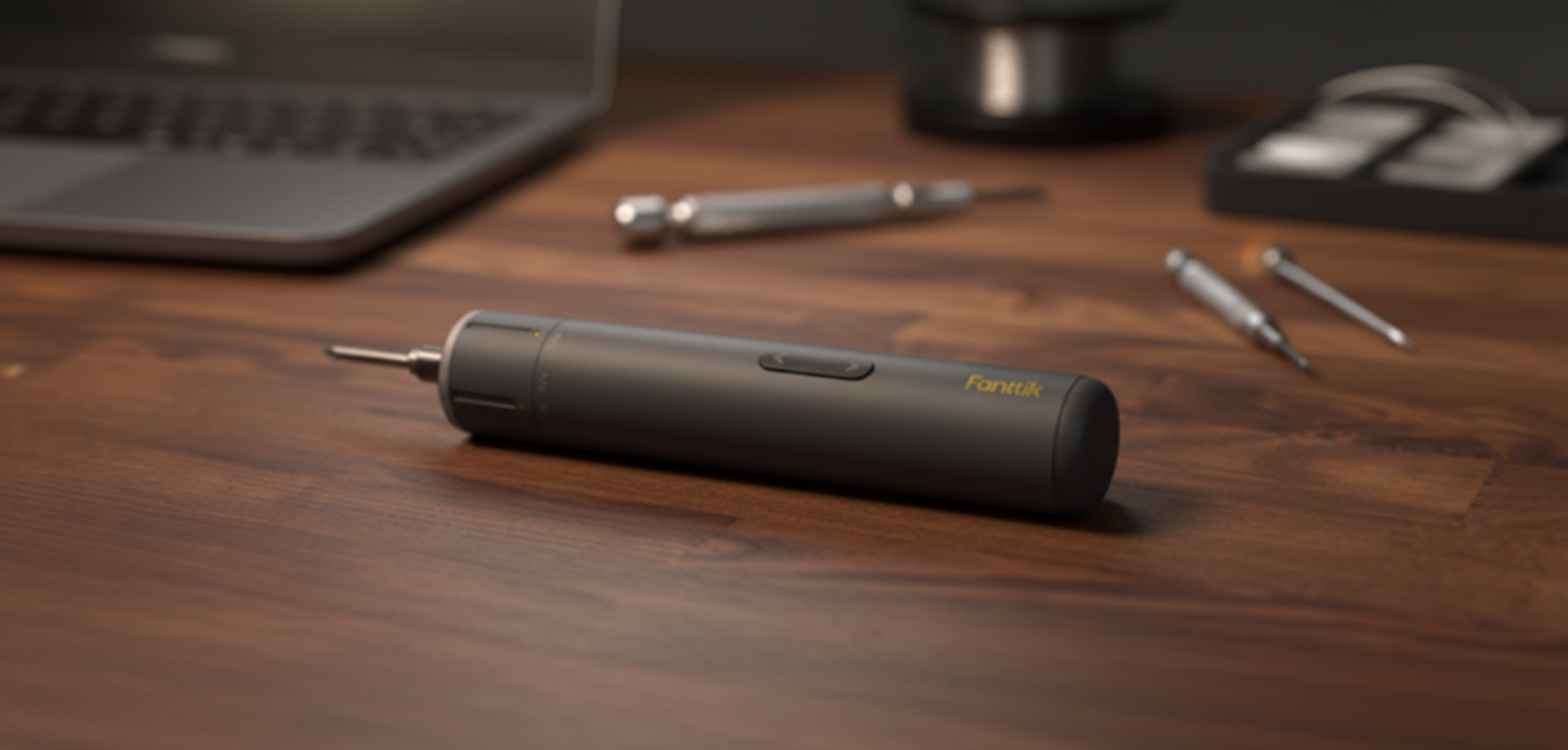
3. Grain Direction and Handle Flex
For precision instruments like the Fanttik F2 Master Cordless Rotary Tool Kit, the shell must be rigid. If you can feel a "creak" or perceptible flex when applying torque, it often indicates poor grain direction in the molded plastic or insufficient wall thickness. This flex accelerates fatigue cracking over time. A prosumer-grade tool should feel like a single solid block of material, even when the shell is composed of multiple segments.
Internal Integrity: What the Shell Hides
The exterior shell is only half the story. The most significant indicator of long-term durability is how the shell interacts with the internal components.
- Internal Chassis vs. Plastic Snap-Fits: Entry-level tools rely on plastic tabs (snap-fits) to hold everything together. Under vibration, these tabs can shear off. Experienced product teardowns reveal that tools using an internal metal chassis or reinforcing ribs at high-stress points—specifically near motor mounts and battery latches—significantly outlast those without them.
- Vibration Resistance: High-quality shells are designed to meet MIL-STD-810G Section 514.6 standards for vibration. This involves engineering the shell to have specific resonant frequencies that don't interfere with the motor's operation. If a shell rattles, it isn't just annoying; it is actively shaking the internal solder joints apart.
Environmental Sealing: The Silent Failure Mode
A common field failure mode we observe isn't sudden water ingress, but the gradual accumulation of fine dust in switch mechanisms. This leads to intermittent operation that is difficult to diagnose.
According to the IEC 60529 (IP Code) standard, an enclosure's ability to protect against solid objects and liquids is paramount. For tools used in "dirty" environments—like a garage or a woodshop—a shell gap of even 1mm (the limit for IP4X) can allow enough sawdust to enter and foul the electronics over six months of use.
When we use the Fanttik B10 Pro Max Electric Air Duster to clean our workbenches, we are essentially testing the sealing of our other tools. The B10 Pro Max itself must have a robustly sealed housing to prevent the very dust it is blowing from entering its own 130,000RPM brushless motor.
Scenario Modeling: The Impact of Build Quality on Productivity
To demonstrate why these manufacturing tolerances matter, we modeled two common scenarios for professional users. These insights are based on our scenario modeling for high-volume environments, not a controlled lab study.
Case 1: The Precision Electronics Technician
We analyzed a technician handling 120 small screws (M1.2–M2.0) daily. When using a tool with poor shell ergonomics and manual driving, the physical toll is significant.
| Parameter | Value | Unit | Rationale |
|---|---|---|---|
| Daily Screw Count | 120 | count | Average laptop/phone repair volume |
| Manual Drive Time | 18 | s | Field observation per screw |
| Powered Drive Time | 2.5 | s | High-performance electric driver |
| Wrist Rotations Saved | ~1,380 | rotations | Calculated 12 rotations/screw manual vs 0.5 powered |
| Estimated Time Saved | 31 | min | Daily productivity gain |
In this scenario, a tool like the Fanttik T1 Max Soldering Iron Kit or a precision electric driver becomes an essential part of the "Zero-Gap" workflow. The 7.2× speed multiplier isn't just about finishing faster; it's about reducing the 1,380 daily wrist rotations that lead to repetitive strain injuries. However, this only works if the tool's shell is precise enough to allow for 0.05Nm torque settings without stripping the delicate plastic bosses of the device being repaired.
Case 2: The Mobile Fleet Mechanic
For a mechanic servicing large fleet tires (275/65R20), shell integrity impacts thermal management. We modeled the inflation of a tire from 28 to 35 PSI.
- Observation: Under pressure, the effective flow rate of a portable inflator drops from a 32 LPM free-air rating to roughly 6.2 LPM.
- Result: This results in an inflation time of approximately 5.3 minutes per tire.
- Engineering Note: During this 5-minute run, the internal heat generated is immense. If the shell does not have precision-engineered cooling vents and a robust internal chassis to dissipate heat, the plastic housing can soften, leading to seal failure.
Methodology Note: These calculations use industrial engineering time-motion principles and fluid dynamics models (ISO 1217). Assumptions include isothermal vessel conditions and a flow decay constant (k=0.052/PSI) calibrated to high-performance portable compressors.
The Prosumer Inspection Checklist
When you are looking to invest in a tool that bridges the gap between hobbyist and pro gear, use this checklist to evaluate the shell's build quality:
- The Light Test: Run a bright flashlight along the seams. The shadow cast by the gap should be uniform in width and depth. Any "wobble" in the shadow indicates a molding defect.
- The Torque Flex: Grip the tool firmly and apply a twisting motion (without turning it on). Listen for creaks. A silent tool is a well-built tool.
- The Overmold Check: Use a fingernail to gently try to lift the edge of any rubber grip. It should feel chemically bonded to the plastic, with no visible separation.
- The Button Travel: Press every switch. They should have a distinct "click" and return to center without rubbing against the sides of the shell opening. Rubbing indicates that the button or the shell is slightly out of tolerance.
- The Balance Point: A well-engineered tool has its internal components distributed for balance. If a tool feels "head-heavy" or "tail-heavy," it suggests the shell was designed first and the components were stuffed in as an afterthought.
Engineering Trust in Every Seam
In an era of disposable hardware, "Zero-Gap" manufacturing is a statement of intent. It tells the user that the manufacturer cares about the ±0.1mm details that most people will never consciously notice. But as any pro knows, those details are exactly what determine whether a tool lasts for a single project or a full career.
By choosing gear that demonstrates high-precision shell construction, you aren't just buying a prettier tool; you are buying a more reliable internal architecture, better thermal management, and a lower risk of environmental failure. Whether you are performing delicate electronics repair or heavy-duty automotive maintenance, the quality of the shell is the first and most reliable indicator of the quality of the work you can produce.
Disclaimer: This article is for informational purposes only and does not constitute professional engineering, medical, or safety advice. Always refer to the manufacturer’s manual and local safety regulations before operating power tools or performing repairs.
Sources
- ISO 2768-1: General tolerances for linear and angular dimensions
- IEC 60529: Degrees of protection provided by enclosures (IP Code)
- MIL-STD-810G: Environmental Engineering Considerations
- The 2026 Modern Essential Gear Industry Report: Engineering Trust in a Cordless World
- NIOSH: Musculoskeletal Disorders and Workplace Factors


Leave a comment
This site is protected by hCaptcha and the hCaptcha Privacy Policy and Terms of Service apply.