









Knowing how to solder a pcb without damaging components comes down to clean tip contact, active flux, and short dwell times. Use a clean, well-tinned iron tip that touches the pad and the lead or terminal at the same time, add only enough electronics flux to help the solder wet, and pull the tip away the moment the joint flows. This limits both the heat and the mechanical stress that lift fragile pads or overheat nearby parts.
The right iron setting always depends on your solder alloy, joint thermal mass, and iron recovery speed. Getting clean joints is less about finding one universal temperature and more about moving heat into the joint efficiently and removing the iron fast. The following steps guide you through setup, soldering, joint inspection, and safe troubleshooting.
What Heat, Flux, and Contact Time Actually Control
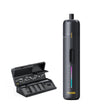
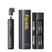
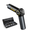
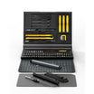
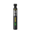
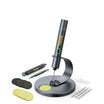
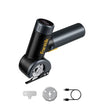
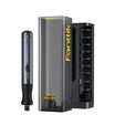
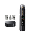
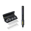
The fastest, safest joints come from good heat transfer, not an aggressively high iron setting. When learning how to solder PCB components without damaging them, tools like the Fanttik T1 Max Soldering Iron Kit pair rapid heating with precise temperature regulation so joints reach flow temperature without lingering heat exposure.
The Joint Must Reach Temperature, Not Just the Iron
Your iron's display reads the tip, not the joint. What actually solders the connection is heat arriving at the pad and lead, and that depends on tip shape, tip condition, iron power, joint mass, and how long the tip stays in contact. A well-maintained tip with efficient heat transfer can solder a joint faster and at a lower risk of collateral heat than a hotter but poorly tinned or undersized tip. Matching tip geometry using C210 replacement soldering iron tips gives you the right thermal contact area for delicate traces versus heavy ground planes. A bigger ground plane or thicker copper pulls heat away faster, so it may need a larger tip contact surface or slightly more dwell, not just a higher number on the dial.
Why Flux Timing Changes the Result
Flux needs to be active while the metal is heating, and it should only be enough to promote wetting, not flood the joint. If you apply too much heat too quickly, the flux can evaporate before it has a chance to clean the surfaces and help the solder flow, leaving a dull or poorly bonded joint even though the iron reached temperature. That is one reason blasting a stubborn joint with more heat often makes wetting worse, not better.
The Damage-Prevention Rule
- Improve contact and tip condition before you reach for a higher temperature.
- Remove the tip as soon as the solder flows and keep the joint still while it solidifies.
- Never use force, prying, or extra dwell time to make a reluctant joint wet or a bridge clear; fix the cause instead.
For SAC lead-free solder, one documented hand-soldering process aims for a connection temperature around 40°C (roughly 72°F) above the alloy's 217°C melting point, reaching a target connection temperature of about 257°C (495°F) held for about 2 to 5 seconds at the joint. That is a bounded process reference for that alloy and setup, not a universal iron display setting; your tip, joint size, and equipment still determine the number you actually dial in.

How to Prepare the PCB and Soldering Setup
Preparation decides whether your first heat cycle goes smoothly. Confirm the board's electrical state and the parts you are working with before the iron ever touches a pad.
Verify the Board and Component Before Heating
- Disconnect the board from power and let any capacitors discharge before you touch it.
- Confirm the replacement or new component's orientation, polarity, and footprint match the board.
- Inspect the target pads for existing lift, corrosion, or damage from a prior repair.
- Note whether the board has a conformal coating that needs local removal before soldering.
- Identify your solder alloy (leaded or lead-free) and choose a compatible flux.
Set Up a Stable, Low-Force Work Area
- Secure the board in a fixture or vise so the iron's contact pressure does not flex it or the component.
- Clean and tin the tip, and set up good lighting, magnification, and ventilation for the joint size you are working on.
- Add ESD controls when the component is sensitive: check the part's datasheet for HBM/CDM ratings and use a grounded, dissipative work surface with personnel grounding. Skip a wrist strap if you are exposed to circuits at 250 volts or higher; de-energizing and discharging the board comes first regardless.
Know When to Stop
Stop as soon as you see coating scorching, a component that discolors or visibly distorts, a pad that moves under light contact, or delamination anywhere on the board. Adding more heat or pressure to rescue a joint that is already showing damage almost always makes it worse; back off and assess the board instead.
How to Solder Through-Hole Components
Through-hole joints depend on wetting both the lead and the plated hole, so the technique centers on heating both surfaces together and holding the lead still while the joint sets.
Install the Component Without Loading the Pad
- Confirm orientation, then seat the component so the lead sits in the hole without bending or forcing it against the pad.
- Support the board so the lead cannot flex the copper pad while you work.
Heat the Lead and Pad Together
- Touch the tinned tip to both the lead and the pad at the same time so heat reaches both surfaces at once.
- Feed solder to the heated joint itself, not to the iron tip, and stop feeding once the solder wets and flows around the lead and hole.
Let the Joint Solidify Before Trimming
Keep the lead perfectly still while the solder solidifies; movement during cooling creates a dull, cracked, or unreliable joint even if it looked fine while molten. Trim the excess lead only after the joint has fully set, then move on to inspection.
How to Solder Surface-Mount Components Without Overheating Them
Small surface-mount joints need less heat overall but tighter control, since nearby parts and pads sit close to your tip.
Tack the Part Before Completing the Joints
- Align the component precisely, then heat and solder just one end or corner to hold it in place.
- Check alignment, reheat that single tack briefly if you need to correct position, then solder the remaining joints one at a time.
Use Flux and Tip Contact Sparingly
Apply just enough electronics flux to support wetting on each pad, and use a fine, well-tinned tip so the contact area matches the joint size. Keep the tip moving to the next joint rather than dragging it across adjacent pads or parts, which spreads heat where you do not want it.
Protect the Component Body
A shiny, wetted joint tells you the solder reached temperature, but it does not tell you the component body stayed within its limit. SMT rework should follow component body temperature limits specified by the manufacturer, especially for heat-sensitive ICs or any part you are reheating more than once. Check that part's datasheet or rework notes before repeating heat cycles on it.
How to Inspect Joints and Catch Damage Early
A quick visual check right after soldering tells you whether to move on or troubleshoot, before the board is buttoned back up.
Check the Joint Shape and Wetting
- Look for a smooth, concave joint where solder clearly wets both the lead and the pad.
- Watch for dull, grainy, or beaded solder, or solder that sits on one surface without bonding to the other.
Check the Board and Component Around the Joint
- Scan for solder bridges between adjacent pads, scorched coating, or discoloration around the joint.
- Confirm the component has not shifted, and that pad edges and the surrounding copper still look intact.
Choose the Next Test
A clean visual pass is a good sign, but it does not prove the electrical connection is sound on its own. Use continuity or functional testing when the circuit's importance calls for it, and avoid probing or flexing a pad you already suspect is weak.
How to Fix Poor Wetting, Bridges, Overheating, and Lifted Pads
Diagnose the cause before adding more heat. Most joint problems trace back to contact, cleanliness, or flux, not an insufficient temperature.

Fix Poor Wetting or a Dull Joint
- Re-tin the tip, clean the pad, and confirm good contact between tip, lead, and pad before touching it to the joint again.
- Add a small amount of fresh flux, then reheat briefly and let the joint solidify undisturbed.
Remove a Bridge Without Pulling the Pad
- Add fresh flux to the bridge, then apply fluxed solder wick with light, pencil-like pressure.
- Move the iron and wick together in a light stroke rather than levering upward or letting them sit frozen on the pad, since that motion and pressure is what actually lifts pads during cleanup.
Stop for Scorching, Overheating, or Pad Movement
Visible coating scorching, an overheated or discolored component, or a pad that has started to separate changes the job from routine soldering to diagnosis. Do not keep heating a pad that is already lifting or a component that is already showing heat stress; document the condition and plan a board-specific repair instead of forcing the original joint to finish.
Once your joints pass visual checks and cool completely, confirm circuit continuity with a multimeter before powering on the board.
FAQs
What temperature should I start with when soldering PCB components?
Start from your solder alloy, not a fixed number. For SAC lead-free solder, one documented process reference targets a connection around 257°C, held only 2 to 5 seconds, but your actual iron setting depends on tip size, joint mass, and equipment. Check your component and board documentation for any lower thermal limits before you commit to a setting.
How much flux should I use when soldering a PCB?
Use only enough electronics flux to help the solder wet the pad and lead; more isn't better. Apply it right before heating so it's still active when the metal reaches temperature, and avoid prolonged heating on a joint that looks dry or over-fluxed, since that just adds risk without improving the result. Clean residues afterward according to your flux's instructions.
Should I keep heating a PCB pad that has started to lift?
No. Stop heating and avoid any pulling or prying force the moment a pad starts to move or separate from the board. A lifted pad needs a board-specific repair approach rather than repeated heat, which only weakens the copper-to-substrate bond further.
Continue reading
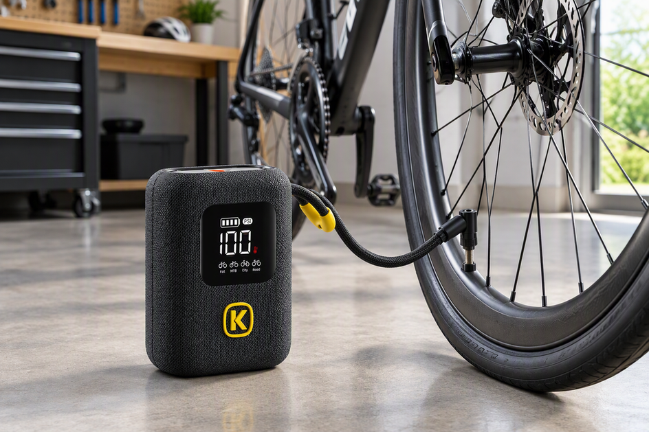 How to Inflate a Road Bike Tire with a Portable Pump
Follow step-by-step instructions to inflate your road bike tire with a portable pump, verify when 100 PSI fits...
How to Inflate a Road Bike Tire with a Portable Pump
Follow step-by-step instructions to inflate your road bike tire with a portable pump, verify when 100 PSI fits...

Leave a comment
This site is protected by hCaptcha and the hCaptcha Privacy Policy and Terms of Service apply.