



















A solder joint needs rework when you find a physical defect, or when a check your project requires shows the joint falls short. Looks alone don't decide it. A joint can look a little rough and still do its job, so compare what you see with what the circuit has to do before you pick up the iron.

This also means reheating shouldn't be your first move. Rework has risks of its own, especially on small surface-mount pads. Save it for joints where you have a real reason to redo them.
When Does a Solder Joint Need Rework?
Rework makes sense when the evidence conflicts with your project's requirements, rather than from cosmetic doubt alone. As the NASA workmanship standard frames it, workmanship must assure that products satisfy the performance requirements of the engineering documentation. In other words, project requirements set the bar rather than surface appearance.
For a home or hobby project, "requirements" means whatever document defines success for that build. It might be a build guide, a repair procedure, or an assembly drawing. Use it to sort your joint into one of these cases:
- You see a physical defect your requirements reject. Rework is justified.
- A check the project calls for fails at that joint. Treat it as a real problem and look closer before you reheat.
- The joint only looks imperfect and passes the required checks. Leave it alone. Reheating adds risk without a documented gain.
- Your project has no written requirements. Use the defect examples in the next section to decide where to look harder. Don't treat them as an automatic pass/fail rule for your build.
This approach keeps solder joint rework tied to evidence. You aren't chasing a perfect look.
What Physical Signs Can Inspection Establish?
Inspection can reveal specific physical conditions that formal standards treat as defects. One example is NASA-STD-8739.2, dated August 1999, which covers certain printed wiring assemblies. For those assemblies, NASA's listed rejection criteria include:
- Cold solder connection
- Overheated solder connection
- Fractured or disturbed solder connection
- Poor wetting
- Insufficient solder
- Solder cracks or fractures
These are rejection criteria for the assemblies the standard covers. They are not a universal checklist for every hobby board. Still, they give you useful names for what to look for. Each one describes something physically wrong with the connection, not just how it looks.
That difference matters when you inspect your own work. A crack or a fracture is a physical break you can point to. Under NASA-STD-8739.2, a dull or frosty appearance is an explicit rejection condition for its covered assemblies, but for general hobby builds, an uneven surface is only an observation until you link it to an applicable requirement or a failed test. Spotting an imperfection tells you where to look, but comparing the joint against your build's specific criteria determines whether action is needed.
How Do Project Requirements and Checks Change the Decision?
Checks connect the joint to what the project actually needs. In the NASA standard, prescribed verification tests build confidence against life and mission requirements. Because tests must match specific operating conditions, no single check settles every joint across every circuit.
If your project calls for a continuity check, run it the way the meter maker describes. Fluke's continuity testing guide lays out the conditions:
- De-energize the circuit.
- Make sure the component you're testing is isolated from other components in the circuit.
- Connect the test leads across that component.
A beep means the meter detected a complete path. Fluke notes that the beep depends on the component's resistance and the meter's range setting. That makes it a narrow result. It shows a path exists under those test conditions. It does not show that the joint is mechanically sound, that it meets your project's requirements, or that the circuit works.
If you get no beep, the meter didn't find a complete path. First confirm that the circuit was off, the part was isolated, and the leads were across the right points. If the setup was right, check the joint for the physical conditions listed above, and evaluate both electrical path continuity and visible fractures according to your project's acceptance criteria.
For anything beyond a simple path check, such as whether a sensor reads correctly or a board powers up, use the functional check in your project's documentation. A continuity beep can't stand in for it.
When to Rework—and Why Not to Keep Reheating
Rework once you have evidence: a listed physical defect, a failed required check, or both. Before you touch the joint, follow your project's own procedure for removing power and isolating the circuit. If the project has none, at least have the circuit de-energized, just as for the continuity check.
Rework is not risk-free. The NASA standard requires that rework cause no electrical or mechanical damage to the part or the assembly. It also gives a specific warning about removing solder with wick. NASA's surface-mount solder-wick warning explains that surface-mount land patterns are fragile, and that moving the wicking braid too much while heat is applied will, in most cases, loosen or completely remove the footprint. A lifted pad turns a questionable joint into a damaged board.

That warning covers one operation, heated braid removal on fragile surface-mount pads. Still, it shows why repeated "just one more pass" attempts are a poor default. Each extra removal pass on a delicate pad is another chance to make exactly that mistake. Plan the rework so you do it once: confirm the defect, pick your removal method, and keep the braid still while it's heating.
If you need to clear solder first, our guide comparing desoldering braid and a sucker pump explains when each method fits. If your bench isn't set up yet, our beginner soldering workstation setup guide covers getting ready and tinning the iron before your next joint.
FAQs
Is NASA-STD-8739.2 the rulebook for hobby electronics?
No. It is a NASA workmanship standard dated August 1999 for the printed wiring assemblies it covers. Its defect list is a useful way to name what you see, but your own project's requirements decide whether a joint passes.
What does "poor wetting" mean on a solder joint?
The NASA standard says solder must wet all parts of the connection. Poor wetting means the solder hasn't flowed onto and bonded with every surface it's supposed to join. In that standard, it counts as a rejection criterion.
My joint looks rough, but the circuit works. Should I redo it?
Not because of how it looks. Reheat only if the joint shows a listed physical defect, such as a crack, or fails a check your project requires. If neither applies, solder joint rework adds risk and gives you nothing you can document.
Can I run a continuity check while the circuit is powered?
No. Fluke's continuity procedure starts with the circuit de-energized and the component isolated from other parts. Turn off power first, then connect the leads across the component you're testing.
Continue reading
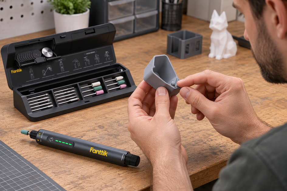 How to Decide Whether a Rotary Tool Is Right for 3D-Print Cleanup
A practical decision guide for makers weighing a rotary tool against hand methods, covering task size, print material,...
How to Decide Whether a Rotary Tool Is Right for 3D-Print Cleanup
A practical decision guide for makers weighing a rotary tool against hand methods, covering task size, print material,...
 How to Make Tent Guy Lines Easier to See at a Busy Campsite
A route-first guide to keeping campers from tripping on tent lines: plan walking paths, flag lines that must...
How to Make Tent Guy Lines Easier to See at a Busy Campsite
A route-first guide to keeping campers from tripping on tent lines: plan walking paths, flag lines that must...
Leave a comment
This site is protected by hCaptcha and the hCaptcha Privacy Policy and Terms of Service apply.