







Choose the largest chisel or bevel face that fits the exposed splice and its surrounding clearance. A broader working face contacts more of the exposed metal on both conductors at once, which generally moves heat into the joint faster than a fine point does.
Switch to a conical tip when the splice sits in a cramped spot, next to other wiring, or where a wide face would risk touching insulation. That access trade-off, not the tip's name, is what should decide the pick for a specific splice.
Which Soldering Iron Tip Should You Use for a Wire Splice?
The deciding factor is whether the working face of the tip can sit against both conductors at once without crowding nearby insulation or components. An open splice with enough exposed metal generally benefits from the broadest chisel or bevel face that physically fits, because that face heats more of the joint at the same time.
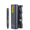
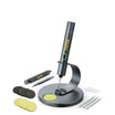
A cramped splice, or one tucked next to other wires, often calls for a conical tip or the narrow side of a smaller face, since access controls what you can safely use. If you are assembling a soldering setup from scratch, tip sets are usually sold as separate accessories rather than fixed to one iron, similar to a replacement soldering iron tip set that swaps between shapes on the same handle.
Why Contact Area Changes Wire-Splice Heat Transfer
A bigger working face touching more of the exposed metal transfers heat into the joint faster than a point contact does, but tip mass, iron power, and how quickly the iron recovers after heat loss still shape how the job actually goes.
What the Contact Patch Actually Does
A clean, wetted, broad face touches more of the exposed wire strands than a narrow point can. Heating both conductors together, rather than one strand at a time, lowers the odds that solder melts on the tip while the wire underneath stays cool. As noted in the Virginia physics department's guide on soldering instructions, a larger contact patch improves heat transfer into the joint, provided the tip and the wire surfaces are clean and the flux is still active when solder is fed in. That is why feeding solder at the point where the soldering iron tip meets the wire, rather than dropping it onto the tip alone, matters more than tip shape by itself.
Why Thermal Recovery Is Not Tip Temperature
Thermal recovery describes how quickly the iron regains its set temperature after a joint pulls heat away from it, and it depends on tip mass, heater design, iron power, and how much thermal mass the splice itself has. A high maximum temperature setting on an iron's spec sheet says nothing about how well that iron actually delivers or recovers heat at a real splice; that is a separate performance question from the number on the dial. Complete kits, such as a cordless soldering iron kit, typically pair the tip with a temperature control so the setpoint and recovery behavior can be adjusted for the job, but neither the setpoint alone nor the maximum rating proves adequate heat delivery for a given splice.

Chisel vs. Bevel vs. Conical: What Changes at the Joint?
No single tip geometry wins every wire splice. Each shape trades usable contact area for access, so the right pick depends on how open the splice is and how much exposed metal needs heat at once.
Geometry, Contact, and Access at a Glance
| Tip geometry | Usable contact behavior | Access trade-off | Bounded wire-splice scenario |
|---|---|---|---|
| Chisel | Wide, flat face contacts more exposed metal at once | Needs open clearance to sit flush | Accessible, larger, or bundled splices |
| Bevel | Angled face with a moderate contact area | Approaches at an angle in partly open spots | Splices with one accessible side but limited full clearance |
| Conical | Narrow point or small side face | Fits tight, crowded, or delicate spots | Cramped splices where a broad face can't sit safely |
In their reference on soldering iron tip shapes, iFixit describes the flat, wedge-style face as offering a wide contact area for joining wires, while noting that the very point of a conical tip is often less efficient for heat transfer than its side, which is why the side of a conical tip is frequently the part actually used against the work.
Read the Table by the Actual Face
Manufacturers name tips inconsistently, so check the working face in front of you rather than trusting the label alone. A broad face only helps if it can touch both conductors without brushing insulation or a neighboring splice. A conical tip is not a fallback choice; it becomes the right one whenever access, not heat transfer, is the limiting factor. When comparing tip options for a broader project kit, sets built for a specific soldering iron are often grouped with other hand tools, similar to the picks in a DIY tools collection.
How to Match Tip Size to Wire and Splice Access
Match the tip to how much exposed metal you have and how much room you have to work in, not to wire gauge alone. Run a quick placement check before you ever turn on the heat.
Use This Four-Branch Selector
- Small and open: use a small chisel or bevel face if it contacts both conductors without crowding the insulation on either wire.
- Small and cramped: use a conical tip or the narrow side of a small face, since access, not heat capacity, is the limiting variable here.
- Larger and open: favor the broadest chisel or bevel face that physically fits the exposed metal to heat more of the joint at once.
- Larger and cramped: pick the face that can still reach both conductors even if it is smaller than you would like; if solder still will not flow promptly, stop and reassess the splice prep or tip fit rather than pushing more heat.
Do a Cold Placement Check
Before heating anything, hold the unheated tip against the splice and confirm the working face reaches both conductors at the intended angle. Check that the handle position does not force the tip into nearby insulation or another wire. If it does not fit cleanly, improve support or swap the tip before you add heat, rather than trying to compensate once the iron is hot.

What Temperature and Heat Delivery Should You Start With?
Solder melting point, iron working temperature, heat delivery, and thermal recovery are four separate things, and mixing them up is an easy way to misjudge a splice. Start from a general practice range, then adjust for the alloy and the joint in front of you.
Keep the Four Heat Metrics Separate
The solder's melting point, or liquidus, is a property of the alloy itself. Iron working temperature is the setpoint you control on the tool. Heat delivery depends on contact area, tip condition, heater power, and how much metal mass the joint has to warm. Thermal recovery is how well the iron holds that setpoint once the joint starts drawing heat away. None of these four numbers can substitute for another.
Use a Starting Point, Then Adjust
- Technical guides commonly cite roughly 572–662°F as a general starting range for everyday electronics work, noting the right setting shifts with the solder, the component or joint size, and how heat-sensitive the parts are.
- In their guide on hand soldering tip temperatures, Indium cites roughly 599°F (315°C) as a suggested hand-soldering tip temperature specifically for Sn63 and SAC alloys, which is an alloy-specific reference point, not a universal wire-splice setting.
- A NASA lead-free solder report puts the melting point of common SAC alloys at roughly 423°F (217°C), which is well below any working iron setpoint and demonstrates why melting point and iron temperature are distinct figures (Lead-Free Solder Body of Knowledge).
- Improve tip contact and wetting before turning up the dial. Extra heat does not fix a joint that the tip cannot properly contact, and it raises the chance of damaging nearby insulation.
How to Heat the Splice Without a Cold Joint or Scorched Insulation
A clean, wetted tip and a joint that flows promptly are the two signs you are doing this right. Work through preparation, contact, and inspection in order rather than adding heat when something looks slow.
A Controlled Wire-Splice Sequence
- Prepare the conductors: strip and twist or hook the wires as needed, and keep the surrounding insulation clear of where solder will flow.
- Clean and tin the tip so solder wets the working face rather than beading on it.
- Place the tip's working face against both conductors at the same time, using the largest face that fits without touching insulation.
- Feed solder at the point where the tip meets the wire, not onto the tip alone, so the joint itself draws in the solder.
- Pull the heat away as soon as the solder has flowed into a smooth, wetted joint, then let it cool undisturbed before moving or sleeving it.
NASA workmanship guidance for its own soldering procedures keeps insulation out of the solder joint entirely and limits iron contact to five seconds for that specific documented step, using only enough pressure to maintain contact (Soldering Program Plan). That time limit applies to NASA's own procedure rather than every consumer splice, but the underlying logic carries over directly: if solder is not flowing within a few seconds of controlled contact, stop and check your tip fit or wetting instead of holding the iron there longer.
What a Failed Joint Tells You
If solder melts easily on the tip but will not flow into the splice, the tip likely is not making full contact with both conductors, or the wire surfaces were not clean enough to wet. A dull, lumpy, or partially flowed joint calls for cleaning the wires, re-tinning the tip, improving support, or switching to a better-fitting face, rather than simply adding more heat. Visible insulation damage, such as softening or discoloration, is a signal to stop and reassess, not a reason to keep going until the solder finally flows.
What Safety Boundary Applies Before Soldering a Wire Splice?
Disconnect the circuit and verify the conductors are de-energized before you strip, position, or solder anything. Do not treat a switch position or an assumption about low voltage as proof of a safe state; if you cannot positively confirm the wire is de-energized, do not proceed with this method.
Control Heat and Material Exposure
- Treat the tip and a just-heated splice as burn hazards until they have cooled.
- Use reasonable ventilation for the solder and flux you are using, and avoid leaning directly over visible fumes.
- Stop heating if insulation softens, discolors, chars, or nearby material starts to degrade; that is a signal to change your approach, not to push through. NASA's soldering standard requires that heat applied to a connection stay compatible with the size and thermal conductivity of the parts involved and specifically prohibits degrading adjacent parts or areas (NASA-STD-8739.3).
- Let the joint and tool cool fully before handling them or fitting insulation over the repair.
The Practical Choice
Use the broadest chisel or bevel face that fits the splice cleanly; drop to a conical tip only when access, not heat capacity, is what limits you. Perform a cold fit check against both unheated conductors, verify proper clearance from surrounding insulation, and test solder flow within the first few seconds before committing to the joint.
FAQs
Is a bevel tip the same as a chisel tip for wire splicing?
Not quite. A bevel tip has an angled working face, while a chisel tip is closer to flat and broad. Manufacturers name these differently across product lines, so judge the actual usable face and how it fits your splice's clearance rather than relying on the label alone.
Can I compensate for a tip that is too small by turning up the temperature?
Not reliably. A higher setpoint does not fix poor contact between the tip and the wire. Improve contact area, clean and re-tin the tip, support the splice better, or switch to a face that actually fits before adjusting temperature, then reassess against an alloy-appropriate starting range.
Why does solder melt on the iron tip but not flow into the wire splice?
Solder melting on the tip only proves the tip is hot enough, not that both conductors have reached soldering temperature. Clean and tin the tip, place it so it contacts both conductors at once, feed solder at that heated junction rather than at the tip alone, and reassess your tip fit if flow still stays slow.
Continue reading
 What Is a Soldering Iron Used for Outside Circuit Boards: Craft, Stained Glass, and Pyrography
See which non-electronics jobs suit a soldering iron, from stained glass and wood burning to the plastic and...
Precision Electric Screwdriver vs Manual Driver: Repairing Laptops and Game Consoles
A practical choice split for laptop and console repair: when powered rotation helps, when manual feel is safer,...
What Is a Soldering Iron Used for Outside Circuit Boards: Craft, Stained Glass, and Pyrography
See which non-electronics jobs suit a soldering iron, from stained glass and wood burning to the plastic and...
Precision Electric Screwdriver vs Manual Driver: Repairing Laptops and Game Consoles
A practical choice split for laptop and console repair: when powered rotation helps, when manual feel is safer,...

Leave a comment
This site is protected by hCaptcha and the hCaptcha Privacy Policy and Terms of Service apply.