






























A dull, grainy, or cracked solder joint is a reason to inspect it, not proof that it has failed. Some suspect joints just need a quick reflow with fresh flux and controlled heat; others hide a defect that a shiny surface won't fix. This guide shows how to read the visual signs, reflow a suspect joint safely, and check whether the repair actually worked instead of just looking better.
Key Takeaways
- Dull, grainy, cracked, uneven, or balled-up solder is a reason to look closer, not proof the joint has failed.
- Likely causes include insufficient heat or flux, contamination or oxidation, poor heat transfer, movement during cooling, or excessive heat that damages the board.
- Reflow with compatible flux and controlled heat, add only the solder you need, and let the joint cool without moving it.
- A shiny finish doesn't prove reliability on its own, especially on hidden surface-mount or through-hole joints; check the fit and test the circuit.
- Stop reheating if a pad lifts or discolors, and never work on an energized or high-voltage assembly.
How to Identify a Cold Solder Joint by Appearance
A suspect joint usually gives itself away through texture and shape, not just color. Look for a fillet that flows smoothly onto both the pad and the lead instead of sitting on top of them like a blob.
Check Texture, Shape, and Wetting
A well-formed joint looks consistent across its whole surface and tapers smoothly from the lead into the pad. Dullness, graininess, roughness, cracks, gaps, uneven distribution, or a balled-up shape are all reasons to investigate further rather than assume the joint is fine. According to a hand-solder rework troubleshooting guide for cold joints, a healthy joint typically shows a smooth, shiny, concave fillet, while a defective one often looks dull, grainy, or cracked.
That said, shine alone doesn't confirm a good connection. A joint can look bright and still lack full contact underneath, so treat appearance as your first screen, not your final answer. Before you reflow anything, compare the suspect joint against a known-good one on the same board so you can judge shape and coverage rather than color alone.
Look Differently at Through-Hole and Surface-Mount Joints
A through-hole joint needs solder to fill the barrel and wrap around the lead, not just look smooth on top. Check both sides of the board when you can, since a shiny top surface can still sit over a hole that never filled properly.
A surface-mount joint hides more of itself under the component body, so the visible fillet may not show the full lead-to-pad contact. Use magnification and angled lighting to catch a partial connection, and plan on a continuity or functional check later in this guide when the joint is partly hidden from view.

What Causes Dull, Grainy, or Cracked Solder?
Most dull or cracked joints trace back to how heat, flux, or contact were handled during the original solder job. Treating the cause correctly matters more than simply reheating the joint.
Heat, Contact, and Movement
The pad, the lead, and the solder all need to reach a working temperature together. Heating only the solder blob while the pad or lead stays cool can leave a joint that never wets properly, even if it looks shiny for a moment. Movement while the solder is still liquid or semi-solid can also leave a disturbed, uneven surface. A large pad, a ground plane, or a heavy lead can pull heat away faster than a small isolated pad, which changes how long contact needs to last, though this guide doesn't set a universal dwell time for that adjustment.
Flux, Oxidation, and Contamination
Insufficient or inactive flux can't remove the metal oxides that block proper wetting. In fact, IPC hand-soldering guidance notes that poor wetting from insufficient flux or inadequate heating can leave defective joints. Dirt, oxidation, and burned flux residue can sit on the surfaces that need to bond and interfere with solder flow. Clean the joint and apply fresh, compatible flux before you extend contact time with the iron, since longer heating on a dirty joint tends to make the surface worse, not better.
When It May Not Be a Cold Joint
A bridge, an overfilled joint, a lifted pad, a damaged lead, or dewetting all need a different fix than a simple reflow. If you reflow a joint and the surface improves but the circuit still misbehaves, treat that visual change as incomplete evidence rather than a finished repair. The inspection and testing section below covers what to do next instead of applying more heat to the same spot.
Tools and Materials for a Controlled Reflow
Before you heat anything, get your iron, solder, flux, and inspection tools in one place. Missing one item mid-repair usually means longer, unnecessary heat exposure on the board.
Core Reflow Equipment
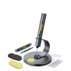
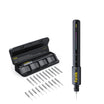
Use a temperature-controlled soldering iron with a tip sized to reach the joint and the connected pad or lead without touching nearby components. A soldering iron kit with interchangeable tips gives you more control over which surfaces the tip actually contacts. Secure the board in a stand or vise so it can't shift while you work, and set up lighting or magnification strong enough to see the pad, the lead, the solder edge, and any nearby bridge.
Solder, Flux, and Cleaning Materials
Match your solder and flux to the existing board and solder system rather than mixing types without checking compatibility. Keep replacement iron tips on hand if your current tip is worn, pitted, or the wrong shape for the joint. Have cleaning material suited to your flux type ready, since not every residue should be treated the same way, and keep a continuity tester or the working circuit itself available for the check described later. You can browse a broader range of hand tools in our DIY tools selection if you need to round out your kit.
How to Reflow a Suspect Solder Joint
Reflowing a suitable, accessible, low-voltage joint follows one controlled sequence: prepare, flux, heat, add solder only if needed, cool, and inspect. Work through the steps in order and stop at the point noted if you see heat damage.
- Disconnect power and batteries, and confirm the assembly is a suitable candidate: low-voltage, de-energized, and free of visibly lifted pads or already-damaged board material. Do not attempt this on an energized, mains-connected, or high-voltage assembly.
- Secure the board in a stand so it can't shift, and clean the joint area if it shows dirt, oxidation, or old flux residue.
- Apply a small amount of compatible flux directly to the joint before you add heat; flux removes oxides so the solder can wet properly.
- Heat the joint and the connected pad or lead, not just the existing solder blob, until the solder visibly melts and flows. According to IPC's hand-soldering guidance, leaving the iron in contact too long or running it too hot can damage components and boards, so stop as soon as the joint reforms.
- Add only the solder needed to complete the connection; adding more than necessary risks a bridge or an overfilled joint that hides the original defect.
- Remove the iron and let the joint cool undisturbed, without moving the board or the component while the solder solidifies.
- Inspect the cooled joint before returning the board to service, using the checks in the next section.
Stop the repair and reassess if a pad, trace, or nearby component begins to lift, blister, discolor, or deform at any point in this sequence.
How to Inspect and Test the Reflowed Joint
Judge the repair only after the board has fully cooled without being moved. From there, the joint either passes, needs more investigation, or means you should stop reheating it.

Use a Pass, Investigate, or Stop Decision
Pass the joint when it shows consistent wetting, proper contact between the lead and pad, no bridge or excess solder, and no visible heat damage, and a continuity or functional check confirms the connection works. Investigate further when part of the joint is hidden, the fill looks uncertain, or the appearance and the circuit's behavior disagree with each other. Stop reheating the same spot if another attempt risks lifting the pad or damaging the board, or if the assembly is outside a simple low-voltage repair.
When Appearance Is Not Enough
A joint that looks improved on the surface can still conceal a real problem. NASA rework documentation emphasizes visual inspection limits for solder joints, noting that surface checks may miss insufficient solder under SMT leads or incomplete through-hole barrel fill, and IPC guidance makes the same point about hidden volume under a component. Run a continuity or functional test appropriate to the circuit rather than relying on looks alone; this guide doesn't provide a universal resistance target because that depends on the specific circuit. If the repaired joint still doesn't restore normal operation, look at a neighboring joint, trace, component, or board fault instead of reheating the same connection again.
FAQs
Can a lead-free solder joint look less shiny and still be acceptable?
Yes. Some solder alloys naturally produce a less reflective finish than others, so brightness by itself isn't a reliable pass or fail signal. Judge the joint by smoothness, consistent wetting, full contact with the pad and lead, and its shape, and confirm the connection with a continuity or functional check when you can.
Should I add more solder every time I reflow a cold joint?
No. Start with compatible flux and controlled heat, since many suspect joints just need to reflow and rewet without any new solder. Only add solder if the connection still looks short after the existing solder has melted and flowed, and check afterward for a bridge or excess solder that the extra material may have created.
What should I do if the solder still won't flow after I apply flux?
Stop extending the heat exposure rather than holding the iron on the joint longer. Instead, check for poor heat transfer, a dirty or contaminated surface, flux that isn't compatible with your solder, or a defect that isn't actually a cold joint. If you notice the pad or board discoloring, lifting, or deforming, stop the repair on that joint and consider a different repair path.
Continue reading
 Smart Home Switch and Outlet Installation: Choosing Insulated Bits and Appropriate Torque
A practical guide to choosing insulated bits, finding verified terminal torque limits, and fastening smart home switches and...
Torque Limits for Furniture Assembly: When to Stop Using an Electric Screwdriver on Particle Board
A practical torque guide for flat-pack furniture: study-backed seating and stripping ranges, plus the exact cues that tell...
Smart Home Switch and Outlet Installation: Choosing Insulated Bits and Appropriate Torque
A practical guide to choosing insulated bits, finding verified terminal torque limits, and fastening smart home switches and...
Torque Limits for Furniture Assembly: When to Stop Using an Electric Screwdriver on Particle Board
A practical torque guide for flat-pack furniture: study-backed seating and stripping ranges, plus the exact cues that tell...

Leave a comment
This site is protected by hCaptcha and the hCaptcha Privacy Policy and Terms of Service apply.