










You can desolder a mechanical keyboard switch without damaging the PCB by fully melting each joint before you apply any suction or force, clearing the solder while it's still liquid, and stopping the moment a switch resists pulling. This works on keyboards with accessible through-hole switch joints, which is the standard construction on most hobbyist boards. Sockets, surface-mount parts, or unusual PCB layouts need a different process and aren't covered here.
Once a switch is out, the pads, holes, and traces need to pass inspection before you solder in the replacement. After that, a quick functional test tells you whether the joint needs more work or the repair is done.
How to Desolder a Mechanical Keyboard Switch Without Pulling PCB Pads
This sequence follows IPC through-hole rework guidance for controlled, non-destructive component removal. Work one switch at a time and don't skip the inspection step at the end.
- Disconnect the keyboard from power and remove the PCB from the case, or otherwise fully expose the switch's solder side.
- Support the board in a vise or holding fixture so it can't shift while you work.
- Identify the two solder joints for the switch you're replacing and confirm they're standard through-hole pins, not a hot-swap socket.
- Prime the desoldering pump by depressing the plunger until it locks.
- Heat one joint with the iron tip until the solder is fully liquid, then position the pump nozzle as close to the molten solder as possible and trigger it.
- If solder remains in the hole, reheat and repeat the pump pass, or finish clearing residue with solder wick, following the same manual pump technique for both leads.
- Check that both leads move freely in their holes before lifting the switch. If it still resists, treat that as a sign solder remains or the joint has cooled, not a reason to pull harder.
- Remove the switch with tweezers, then move to inspection before fitting the replacement.
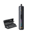
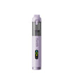
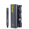
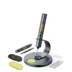
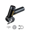
Choosing the right tip size matters when the switch pins sit close together; iron tip options sized for fine-pitch work can make step 5 easier to control.
What Tools and Safety Setup Do You Need?
Beyond the iron and pump, the setup that matters most is a stable board, good lighting, and basic hygiene if the solder contains lead.
- A temperature-controlled soldering iron with a fine tip
- A manual desoldering pump, plus solder wick as backup
- Fresh solder to add to the tip for better heat transfer
- Isopropyl alcohol or flux remover and a lint-free applicator
- Tweezers for lifting the switch once it releases
- A vise or "helping hands" fixture to hold the PCB steady
- Bright, direct lighting and safety glasses
- Local fume extraction or a well-ventilated work area
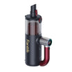
Keep the keyboard unplugged for the entire job, and never solder on a powered device. If the solder may contain lead, OSHA lead exposure guidance notes that lead can contaminate hands, clothing, and food, so keep drinks away from the bench, wash your hands after handling solder or residue, and wipe down the work surface when you're done. These are proportional home-workbench habits, not the workplace exposure limits OSHA sets for industrial settings. A dust collector such as an electric air duster can help clear loose flux and debris from the case before final assembly.

How Iron Temperature, Thermal Capacity, and Recovery Affect the Joint
A high maximum temperature on the display doesn't guarantee a clean joint. What actually clears solder is how much heat the tip delivers into the joint and how fast it recovers after contact.
Temperature Is Not the Same as Heat Delivery
The number on the iron is a setpoint, not a measurement of what reaches the solder. Tip geometry, how firmly the tip contacts the joint, the iron's thermal mass, and the copper in the board all affect whether the solder stays liquid long enough for the pump to work. If a joint keeps re-solidifying before you trigger the pump, the fix is better contact and a larger or cleaner tip, not just a higher setpoint. Adding a small amount of fresh solder to the tip before touching the joint improves heat transfer and is a common technique, not proof that a single pass will always clear the hole.
Use Starting Examples, Not a Universal Setting
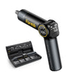
iFixit lists roughly 570°F for leaded solder and 700°F for lead-free solder as working temperatures with a temperature-controlled iron. Those are source-specific examples, not a universal keyboard setting, and the right number for your board depends on the solder alloy, tip, and iron model. IPC time-temperature guidance frames rework around controlled, non-damaging heat cycles rather than a fixed dwell time, so if a joint isn't clearing, repeat a short controlled cycle instead of holding the iron on the pad longer. A temperature-controlled soldering iron that holds its setpoint under load makes this easier to manage than one that cools sharply on contact.
How to Inspect the PCB Before Installing a Replacement
Continue to the replacement only if the board still looks structurally sound around the switch you removed.
What to Inspect
Look at both sides of the board if you can access them. Check that the solder holes are clear, the pads are still fully attached and flat against the board, and the traces leading away from the pads show no lifting, cracking, or discoloration. Use bright light and magnification if the pads are small, but remember that a pad looking intact doesn't confirm the electrical path underneath is good; that's what the functional test in the next section is for.
When to Stop
If a pad, land, or trace is visibly lifting, separating from the board, or delaminating, stop the ordinary replacement process. Don't try to hide the damage with more solder or more heat. This kind of conductor damage falls outside a standard switch swap, and pushing ahead risks turning a bad joint into a bad board.
How to Solder the Replacement Switch Correctly
Before you heat anything, compare the replacement switch's pins, housing shape, and orientation against the one you removed or against the keyboard's documented layout. Exact compatibility is specific to the keyboard and switch design, so don't assume every switch fits every board just because the pin count looks similar.
Seat the switch fully in the plate and PCB so the pins sit flush in their holes without straining the board when you handle it. Solder each pin with a clean joint: enough solder to fully wet the pad and pin, without flooding onto neighboring contacts or leaving a dry, dull surface. IPC J-STD-001J covers thermal protection and post-rework cleaning for soldered assemblies like this one, so wipe away flux residue with isopropyl alcohol once both joints have cooled. Inspect both connections visually for bridging or missed contact before you move on to testing.
How to Test the Key and Troubleshoot It in Order
Reassemble the keyboard enough to test the key, then work through problems from the simplest to the most serious.
If the Key Is Dead
Check switch seating first, then pin alignment, then whether both joints show full, shiny solder coverage with no bridges to neighboring pins. Compare the key's feel and travel with a known-good neighboring switch if the layout allows it; a dead key right after replacement usually points to the joint or seating, not a defective switch.

If Solder or the Switch Still Will Not Release
Go back to the molten-joint check: heat the joint until you can see the solder flow, then run one more controlled pump or wick pass. Don't turn ongoing resistance into a reason to add more force or hold the iron on the pad longer than a normal cycle.
If the Pad or Trace Looks Damaged
Stop the ordinary replacement path. Don't attempt to bury visible pad or trace damage under fresh solder. Repairing a lifted conductor or land is a separate board-level job outside a standard switch swap and isn't something to solve by reheating the same spot repeatedly.
FAQs
Can I use this method on any mechanical keyboard PCB?
This procedure is for accessible through-hole switch joints, which cover most hobbyist keyboards. A socketed hot-swap board, a surface-mount design, or an unusual PCB layout calls for a different, board-specific process, so confirm the joint type before you apply heat or force.
Does a portable soldering iron work for this repair, or do I need a benchtop station?
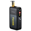
A portable iron can work if it reaches and holds a stable melting temperature at the joint despite the heat the pump pulls away. The deciding factor is thermal capacity and recovery speed, not just the maximum temperature listed on the iron, so an iron that cools sharply on contact will need more repeat cycles than one that recovers quickly.
Do I need special ventilation for a single-switch repair?
Even a small job benefits from basic fume capture and hygiene if the solder may contain lead, since OSHA lead exposure guidance notes that lead residue can transfer to hands and surfaces regardless of job size. A well-ventilated room and washing your hands afterward are proportional steps for a one-switch repair; you don't need workplace-level engineering controls for an occasional hobby task.
Continue reading
 How to Anchor a Tent in Loose Beach Sand
A practical guide to keeping tent guy lines secure in loose, shifting beach sand, covering sand stakes, deadman...
How to Anchor a Tent in Loose Beach Sand
A practical guide to keeping tent guy lines secure in loose, shifting beach sand, covering sand stakes, deadman...

Leave a comment
This site is protected by hCaptcha and the hCaptcha Privacy Policy and Terms of Service apply.