







A soldering iron for electronics work typically runs between 600°F and 700°F, well above the melting point of the solder itself. Leaded solder needs about 600–650°F, and lead-free solder needs about 650–700°F to melt reliably and bond to the joint.
Heat beyond that practical range doesn't speed up the job; it accelerates oxidation, burns flux, and shortens tip life. Understanding how hot does a soldering iron get helps you balance joint heat transfer with proper tip care.
How Hot Does a Soldering Iron Get for Electronics?
Electronics soldering runs in a narrow band tied to the solder alloy, not one universal number. The table below sets the practical starting range, and the notes after it explain when to move away from it.
A Practical Starting Range for Leaded and Lead-Free Solder
| Solder type | Practical starting range | What moves the setting |
|---|---|---|
| Leaded | 600–650°F (316–343°C) | Joint size, tip contact, heat loss |
| Lead-free | 650–700°F (343–371°C) | Larger pads, ground planes, connectors |
These bands come from common soldering iron temperature guidance for hand electronics work, not a fixed manufacturer spec. Treat them as a starting point and adjust based on the joint in front of you.
Why the Iron Setting Is Hotter Than the Solder Melting Point
The tip has to heat both the solder and the metal surfaces of the joint, not just melt solder floating in air. That's why the practical setting sits well above the alloy's melting range. A larger joint, a ground plane, or a bulky connector pulls heat away faster, so it may need more heat delivered through better tip contact or geometry rather than an unlimited increase in temperature.
Why Can a Soldering Iron Run Too Hot?
An iron without accurate tip-temperature feedback can drift outside the useful range as it idles or loses heat into a joint. Closed-loop feedback keeps the tip closer to a chosen setpoint, but that's a different property than how high the iron can go.

What an Unregulated Iron Does Differently
Without a sensor reading the tip itself, heater behavior may rely on fixed power delivery, simple on/off cycling, or a basic thermostat. Temperature can rise while the iron sits idle with nothing drawing heat away, then drop again once it touches a joint. This isn't the same as every simple iron running past any specific number; it just means the tip temperature isn't being measured and corrected the way a closed-loop system does.
How PID Feedback Changes Heater Behavior
A sensor at the tip supplies a temperature reading. The controller compares that reading against the setpoint you selected, then adjusts heater output to close the gap. PID technology in a soldering iron works this way: it's a control method that reacts to heat loss and drift, not a guarantee of zero overshoot or perfect stability under every load.
Why Maximum Temperature Is Not Control Quality
- A high maximum temperature only tells you the top of the selectable range.
- It doesn't prove tip-temperature accuracy, overshoot behavior, or recovery speed under load.
- A documented temperature range can be reported honestly without calling the underlying control system PID.
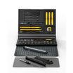
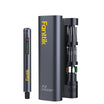
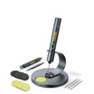
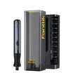
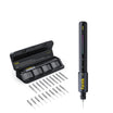
As one documented example, our T1 Max soldering iron kit lists six selectable levels from 390°F to 840°F along with a sleep mode after inactivity and an automatic 15-minute shutdown. That spec sheet shows a selectable range and idle-management behavior, not a measured control-loop test, so it should be read as documented features rather than proof of stability by itself.
Why Does a Soldering Iron Tip Turn Black and Stop Wetting?
A black tip can mean simple residue, oxidation, or real plating damage, and color alone doesn't tell you which. Whether solder still wets the tip after cleaning is the more decision-relevant sign.
Black Residue Versus Oxidation
Blackening on a tip can come from burnt flux residue, surface oxidation, or a combination of both. Since color alone can't separate the two, the more useful test is whether solder spreads and coats the tip once it's been cleaned and re-tinned. If wetting returns after that attempt, the surface itself is probably still fine.
Why Solder Stops Wetting
A contaminated or oxidized surface keeps molten solder from coating the tip evenly. Instead of spreading over the working area, the solder beads up or balls off to one side. That poor contact reduces heat transfer at the joint, which can make a genuinely hot iron feel cold or sluggish to the person using it. Extended time at high heat or long idle periods with the tip exposed can speed up this oxidation and wetting loss, so it's worth treating heat and idle time as contributing factors rather than assuming the iron is simply too cold.
When Plating Damage Changes the Diagnosis
- Inspect the surface. Visible pitting or corrosion means the protective plating over the copper core has been compromised, not just coated in residue.
- Test wetting after cleaning. If fresh solder still won't coat the tip after an appropriate cleaning and re-tinning attempt, treat it as a plating problem.
- Stop treating it as ordinary residue. Exposed or eroded plating won't respond to more cleaning; it needs replacement.
How Can You Prevent Repeat Tip Damage?
Start with the setting and the iron's control behavior before touching anything else. Only after that should you adjust technique or hardware for the specific joint.
A Prioritized Check Before Changing the Temperature
- Verify the setpoint and confirm the iron actually reaches and holds it rather than drifting.
- Start within the alloy-specific range: around 600–650°F for leaded solder, 650–700°F for lead-free.
- Check whether solder wets the tip cleanly and whether the tip is clean and freshly tinned.
- Only then adjust tip geometry, contact, or heat delivery for the joint you're working on.
Match Heat Delivery to the Joint
Large copper areas, ground planes, and bulky connectors pull heat away faster than small pads, so they can look like a "too cold" problem even when the setpoint is correct. A tip shape suited to the joint and solid physical contact improve heat transfer without simply raising the dial further. These adjustments apply to electronics work specifically; don't carry them over to plumbing, stained-glass, or jewelry soldering, where solder types, joint sizes, and heat requirements are different.
When Should You Replace the Tip or Iron?
Before cleaning, retinning, removing, or replacing a tip, switch off and unplug the iron and let it cool completely. With that out of the way, the decision comes down to whether the surface is still intact and whether solder wets it again after a reasonable attempt.
When a Tip Can Be Recovered
- The working surface still looks intact, without visible pits or exposed copper.
- Using an appropriate chemical tip tinner can help restore wetting when the issue is limited to surface buildup or mild oxidation.
- Recovery only counts as successful once solder wets the tip and spreads normally again.
When Replacement Is the Correct Fix
- Replace the tip when there's visible pitting, corrosion, or plating loss, or when non-wetting persists after a proper cleaning and retinning attempt.
- If a known-good, correctly seated tip still behaves erratically, the problem is more likely the iron's heater or control behavior than the tip.
- For a T1 Max whose tip is worn beyond recovery, C210 replacement tips for T1 Max are documented as compatible and carry an anti-corrosion layer intended to resist oxidation.
If your tip takes solder cleanly after retinning, keep working at the lowest effective heat setting; if pitting is visible or solder continues to ball up, install a fresh tip before your next joint.

FAQs
Is the solder melting point the same as the soldering iron temperature?
No. The alloy's melting range is lower than the iron's practical working setting, because the tip also has to heat the joint's metal surfaces, not just melt solder in the air. Start with the supported alloy range, around 600–650°F for leaded solder or 650–700°F for lead-free, and adjust only for how much heat the joint pulls away.
Can a temperature-controlled soldering iron still burn flux or damage tips?
Yes. Control helps hold a setpoint more consistently, but it doesn't remove the effects of the setpoint you chose, how long the tip sits idle and exposed, flux exposure, or existing tip condition. Use the lowest effective setting for the joint and keep the tip clean and freshly tinned during the work session.
Why does solder ball up on a tip that seems hot?
Solder balling up instead of spreading is consistent with an oxidized or contaminated surface that won't let solder wet it, not necessarily an iron that's too cold. Raising the temperature further usually doesn't fix a wetting problem. Try cleaning and re-tinning the tip first, then check whether solder coats it normally again.
Should you clean or replace a soldering tip while the iron is hot?
No. Switch off and unplug the iron, then let it cool completely before you clean, retin, remove, or replace the tip. Skipping this step risks burns and unnecessary contact with a live heating element, regardless of how minor the maintenance task seems.
Continue reading
 What PSI Should Road and Gravel Bike Tires Be? Rider Weight and Width Calculation
A practical method for picking a starting road or gravel tire PSI from loaded weight, tire width, and...
What PSI Should Road and Gravel Bike Tires Be? Rider Weight and Width Calculation
A practical method for picking a starting road or gravel tire PSI from loaded weight, tire width, and...
 Hoverboard Battery Safety: UL 2272 Certification and Safe Charging Habits
Understand how UL 2272 testing and BMS protection mitigate risks, why matching your charging hardware matters, and which...
Hoverboard Battery Safety: UL 2272 Certification and Safe Charging Habits
Understand how UL 2272 testing and BMS protection mitigate risks, why matching your charging hardware matters, and which...

Leave a comment
This site is protected by hCaptcha and the hCaptcha Privacy Policy and Terms of Service apply.