









Start a temperature-controlled iron around 365°C (±10°C) for leaded solder or 380°C (±15°C) for lead-free solder, then rely on a broad, clean, pre-tinned tip to move heat into the XT60 contact and 12 AWG wire quickly rather than pushing the iron hotter. The housing does not melt because of the number on the iron's display; it melts because heat lingers in the nylon while you wait for solder to flow. Keep the battery fully disconnected, pre-tin both parts, and finish the joint in one controlled pass, then inspect the connector before you cover it with heat shrink.
What Temperature Should You Use for XT60 Soldering?
The iron's working temperature and the solder's melting range are two different numbers, and confusing them is why some joints either fail to wet or cook the housing. Connector-focused technical guidance puts a practical starting point at 365°C (±10°C) for leaded solder and 380°C (±15°C) for lead-free solder, values drawn from published XT connector temperature guidance rather than an official XT60 specification.
Treat that figure as a starting point you adjust, not a fixed rule. If solder does not flow onto the contact within a couple of seconds at that setting, the fix is better contact area and cleaner tip prep, not a higher number on the dial, a point general electronics sources make when they stress electronics soldering tip contact area and heat transfer over raw temperature.
It also helps to know what the connector's own spec sheet is not telling you. The documented XT60-F variant lists a housing, contact plating, and a −20°C to 120°C work-temperature range, but that figure describes normal operating conditions for a connected battery lead, not how much heat the nylon can absorb from a soldering iron. The XT60-F operating-temperature range is not a soldering-process limit, so it should not be used to justify longer dwell time at the tip.

Set Up Heat Delivery Before You Touch the Connector
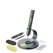
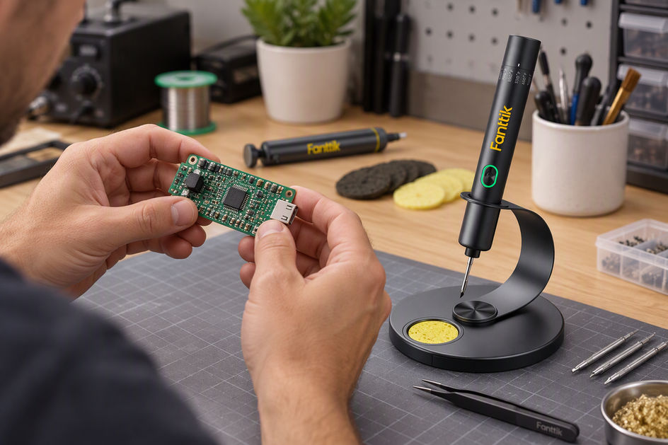
A clean, tinned chisel or hoof-style tip with enough surface area to touch the cup and wire together will heat the joint faster than a fine point at the same temperature setting, and faster heating is what actually protects the housing. The goal is to bring the wire and contact up to soldering temperature together, then let solder flow and pull away, rather than parking a small tip against the cup and waiting.
Before you touch the connector, confirm your solder type (leaded or lead-free), match your iron setting to it, and have flux on hand if your solder does not already contain enough. Specialist electronics guidance is explicit that matching tip size to the contact and heating the lead and pad at the same time shortens the time both are exposed to heat, since tip contact area and heating the wire and contact together determine how quickly the joint reaches temperature.
If the iron loses heat quickly, or solder beads up on the tip instead of wetting the cup, stop. That is a heat-delivery problem, not a signal to hold the iron there longer. Clean and re-tin the tip, let the connector cool fully, and try again with better contact rather than repeating a long heat cycle on the same spot. Repeated reheating is what drives the most heat into the polyamide housing, more than any single well-executed pass at the recommended starting temperature.
How to Solder 12 AWG Wire to an XT60 Contact
Work through this sequence in order, since each step sets up the next one and skipping ahead is what usually causes a rushed, overheated joint.
- Disconnect the battery and slide on heat shrink. Confirm the lead is fully disconnected from any pack, then thread a length of heat-shrink tubing onto the wire before you solder anything, since you cannot add it afterward.
- Check polarity and trim the wire. Match the XT60 housing's polarity marking to the correct wire, and cut the 12 AWG conductor to length with a clean, square end.
- Strip and gather the strands. Strip only enough insulation for the conductor to reach the bottom of the contact cup, then twist any loose strands together so none stick out past the insulation.
- Pre-tin the wire. Heat the stripped conductor and feed solder in until it wicks through the strands evenly. The wire should look uniformly coated, not blobbed, and this step is done once solder flows into the middle of the bundle.
- Pre-tin the XT60 cup. Heat the empty contact cup and add a light layer of solder to its inner wall, without overfilling it. This lets the final joint form quickly instead of needing a long first heat cycle on the connector itself.
- Make the final joint in one pass. Bring the tinned wire and tinned cup together, apply heat to the metal only until the existing solder re-flows, then push the wire fully into the cup while it is still liquid.
- Hold everything still while it cools. Remove the iron and keep the wire and connector motionless until the joint solidifies. Movement during cooling is a common cause of a joint that looks solid but has a fractured, high-resistance connection.
- Inspect before shrinking the tubing. Confirm the wire is fully seated, the solder wets the cup with a smooth fillet, and no stray strand or solder bridge could touch the opposite polarity contact. Only slide and shrink the tubing once this check passes.
Because both parts are pre-tinned, the final joint should need only a few seconds of direct heat, which is the main reason this sequence keeps housing exposure short.

When to Replace an XT60 Instead of Using It
Reuse the connector only if the housing keeps its shape, the contact stays aligned, the joint is fully wetted and seated, and the connector still mates securely. Any one of those failing is a reason to replace it rather than rework it.
XT60 connectors are documented with a polyamide housing and brass contact construction, and that same documentation lists an operating range rather than a soldering exposure limit, so there is no published number that tells you exactly when the plastic has taken on too much heat. Visible condition is the practical signal instead. Check for warping, softening, discoloration, or cracking around the contact, confirm the brass contact has not shifted or loosened in its socket, and verify the connector mates with the same resistance and fit as a new one.
On the electrical side, look for a smooth solder fillet that fully wets both the cup and the conductor, with the wire seated to the bottom and no exposed strand or bridge that could reach the opposite pole. Check the silicone insulation near the joint for cuts, shrink-back, or melted spots. If the housing has changed shape, the contact has moved, insulation is damaged, or the connector no longer mates securely, replace it. Do not begin or continue this work on a connector that is still attached to a live or connected battery; disconnect it first and keep the exposed conductors from touching each other or any other conductive surface until the joint is complete and inspected.
FAQs
Can I leave the mating XT60 connector plugged in while soldering?
On a fully disconnected harness, plugging in the mating half can help hold the housing and contact aligned while you work, since it keeps the two halves from shifting relative to each other. That is different from battery-side work: never treat a mating connector as a substitute for disconnecting the battery, and never let it create a path where exposed positive and negative contacts could touch. Isolate the battery first, then decide whether the mating half is useful as an alignment aid for that specific harness.
Continue reading
 How to Guy Out a Camping Tent on Solid Rock or Hard-Packed Ground
This guide walks through picking a stable site, tying off to a tent's guy points, choosing rock or...
How to Guy Out a Camping Tent on Solid Rock or Hard-Packed Ground
This guide walks through picking a stable site, tying off to a tent's guy points, choosing rock or...
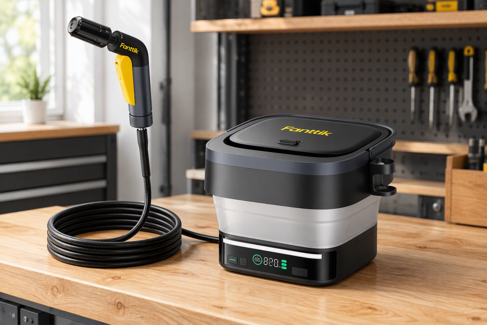 Cordless Battery Pressure Washer Buying Guide: Siphon Power, PSI, and Portability
A practical framework for matching a cordless pressure washer's water source, pressure, flow, and runtime to your actual...
Cordless Battery Pressure Washer Buying Guide: Siphon Power, PSI, and Portability
A practical framework for matching a cordless pressure washer's water source, pressure, flow, and runtime to your actual...

Leave a comment
This site is protected by hCaptcha and the hCaptcha Privacy Policy and Terms of Service apply.