




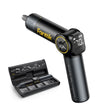
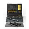
Choosing a soldering iron for circuit board repair comes down to matching temperature control, heat delivery, ESD evidence, and tip access to the job in front of you. For lead-free hand soldering, 700–800°F is a practical starting range, and 63/37 solder can sometimes work as low as 650°F. Fine-pitch surface-mount joints need reliable, low-contact access, larger through-hole joints need more heat transfer, and repeated bench work rewards proven recovery behavior more than a high maximum-temperature spec.
Look for documented tool-level ESD leakage and tip-to-ground test results before working near sensitive components. An adjustable temperature dial alone does not prove an iron is ESD-safe.
Key Takeaways
- Start lead-free PCB soldering around 700–800°F, or as low as 650°F for 63/37 solder, then adjust for joint size, flux, and board construction.
- Thermal capacity and recovery, not maximum temperature, determine how an iron handles repeated joints.
- Verify documented tool-level ESD leakage and tip-to-ground results separately from your bench's overall ESD setup.
- Choose the smallest tip that still makes full contact with the joint; a chisel tip often transfers heat better than a fine point on larger pads.
Which Soldering Iron Fits Your PCB Repair Job?
The right soldering iron depends on the joint scale and how often you work on boards. Match its control, heat transfer, ESD evidence, and tip access to the specific PCB repair task instead of shopping by a single headline spec.
Fine-Pitch SMD Repair
Fine-pitch surface-mount work rewards controlled, repeatable heat and a tip that reaches a single pad without bridging its neighbors. Because these boards often carry sensitive chips, documented tool-level ESD behavior matters here more than on simpler through-hole boards. Prioritize a tip that contacts the joint cleanly without forcing prolonged contact to get a good wet.
Larger Pads and Through-Hole Joints
Bigger pads and leads pull heat away faster, so tip contact area and heat-transfer capacity matter more than pinpoint access. A broader tip is often more useful here than an ultra-fine point, since it can deliver heat to the joint without lingering. Access is still a factor, but it usually takes a back seat to getting the joint hot enough to flow solder cleanly.
Occasional Versus Repeated Bench Repair
If you solder occasionally, a straightforward adjustable iron with a compatible tip and clear control usually covers the job. Repeated bench repair puts more joints through the tip in a row, which is where thermal recovery becomes decisive. Evaluate recovery by whether the iron maintains joint temperature during consecutive solder points rather than relying on spec-sheet wattage numbers.

How Temperature Control and Thermal Recovery Affect PCB Repair?
Temperature control on a soldering iron actually involves several distinct specs, and mixing them up leads to the wrong iron for the job. Start with the solder-specific range below, then adjust for the actual joint and board in front of you.
Working Temperature Is Not the Solder Melting Range
The solder alloy's melting behavior and the iron's working temperature are two different things. For lead-free hand soldering, a 700–800°F starting range is practical guidance, and 63/37 solder has been used at temperatures as low as 650°F. Treat these figures as a process starting point rather than a universal PCB requirement, since the right setting still depends on the alloy you're using and the joint you're working on.
Why Thermal Capacity and Recovery Matter
A joint draws heat away from the tip the moment contact is made, and thermal capacity is what lets the iron keep delivering enough heat to flow solder anyway. Recovery describes how quickly the tip's working temperature returns after that initial heat loss. Recovery matters when moving through consecutive joints, whereas initial heat-up speed or headline wattage numbers do not indicate how well an iron maintains working heat under continuous joint load.
How to Adjust Without Chasing Heat
Start within the solder-specific range, then improve tip contact and wetting before turning the dial higher. Prolonged contact and excessive heat raise the risk of board and component damage, so a joint that won't wet is usually a tip, flux, or contact problem rather than a temperature problem. Board construction, joint size, flux type, and component heat limits are the variables most likely to move your setting away from the starting range.
What Makes a Soldering Iron ESD-Safe for PCB Repair?
An iron's ESD suitability should rest on documented tool behavior, not on a product label or an adjustable dial. Keep that tool-level evidence separate from your bench's overall ESD setup.
What Tool-Level ESD Evidence Means
Look for documented tool leakage and resistance testing performed on the specific soldering iron, measuring electrical leakage and tip-to-ground resistance to verify EOS-safe operation for a hand tool. That evidence describes the tool itself, not the bench it's used on or the process around it.
What the Iron Test Does Not Prove
Passing tool-level leakage and tip-to-ground checks does not by itself verify your mat, wrist strap, grounding path, or handling process, and it does not guarantee that a sensitive component survives the repair. Treat ESD control as a system: the iron is one part of it, and the rest of the bench still needs its own setup and habits to close the gap.
Which Soldering Iron Tip Should You Use for PCB Repair?
Tip geometry decides whether the iron can reach the joint and deliver enough heat without lingering there. A fine point is not automatically the safest PCB choice, since a broader tip can move more heat into the joint when it still fits. Use the table below to match tip shape to the joint you're working on.
| Tip geometry | Best-fit PCB scene | Heat-transfer/use boundary |
|---|---|---|
| Fine point / conical | Fine-pitch SMD pads, densely spaced leads | Good access, but not suited to every application where more heat needs to reach the joint |
| Chisel | Larger through-hole joints, ground planes | Transfers more heat to the joint when contact area allows it |
| Bevel / hoof | General-purpose pads with moderate spacing | Balances some access with more contact area than a fine point |
Pick the smallest tip that still makes full, reliable contact with the pad or lead. Forcing an oversized tip against a fine-pitch pad risks bridging neighboring pins, while an undersized tip on a larger joint can stretch out contact time instead of shortening it.

How Do You Use and Troubleshoot an Iron on a PCB?
Work through the board and bench setup before the iron ever touches a joint. This sequence keeps the process consistent and reduces the chance of chasing heat when a joint gives you trouble. If your bench still needs the right consumables, a guide to soldering iron kit essentials covers what's actually useful before you start.
- Disconnect power and inspect the board and component for existing damage, corrosion, or lifted material before applying any heat.
- Set up your ESD-controlled work area, mat, wrist strap, and grounded iron, before handling ESD-sensitive components.
- Confirm the tip geometry from the table above is clean, properly tinned, and appropriate for the joint you're about to work.
- Set the iron within the solder-specific starting range, around 700–800°F for lead-free or as low as 650°F for 63/37, and confirm the joint wets promptly.
- Apply the tip with full, brief contact rather than a long dwell, and avoid reworking the same joint repeatedly if it doesn't wet on the first attempt.
- Stop heating and stop applying force immediately if the pad or trace begins to lift or deform. Let the joint cool, then recheck tip condition, flux, solder compatibility, and contact before trying again.
FAQs
Is 700–800°F safe for every PCB repair?
No. It's practical guidance for lead-free hand soldering, not a universal PCB setting. Solder alloy, joint size, flux, board construction, and component heat limits can all call for a different starting point, and reheating the same joint repeatedly is generally riskier than adjusting your tip contact or flux first.
Does adjustable temperature mean a soldering iron is ESD-safe?
No. Temperature control and ESD behavior are separate capabilities, and an adjustable range says nothing about a tool's electrical leakage or tip-to-ground resistance. Confirm documented tool-level ESD test results before treating an iron as suitable for ESD-sensitive work.
What does tip-to-ground testing tell you about an ESD soldering iron?
It tells you how the tool itself performs on electrical leakage and resistance from the tip to a ground reference, which is the recognized way to check EOS-safe operation for a hand tool. It doesn't verify your mat, strap, or grounding path, and it doesn't guarantee that a component survives the repair.
Continue reading
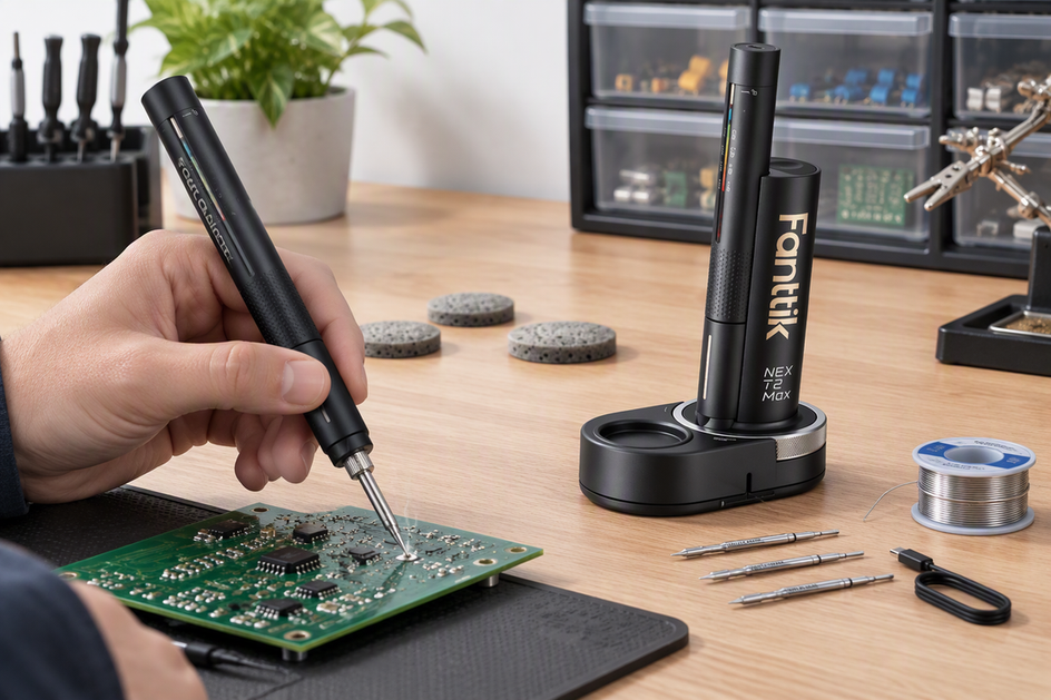 Cordless Soldering Iron Buying Guide: Battery Life, USB-C PD, and Heat-Up Time
A practical framework for matching cordless soldering iron specs, from heat-up and recovery to battery runtime and USB-C...
Cordless Soldering Iron Buying Guide: Battery Life, USB-C PD, and Heat-Up Time
A practical framework for matching cordless soldering iron specs, from heat-up and recovery to battery runtime and USB-C...

Leave a comment
This site is protected by hCaptcha and the hCaptcha Privacy Policy and Terms of Service apply.