









To fix a solder bridge between two PCB pins, first confirm that those pins are supposed to be separate. Next, make sure the circuit is fully de-energized. Then remove the extra solder with a controlled method, such as desoldering braid on accessible leads, and inspect the result before you power the board again.

Never scrape at a bridge on live electronics. Some solder connections are there on purpose, and not every bridge can be reached cleanly with a hand iron. The checks below help you decide whether solder bridge repair is a job for your bench or one to stop and hand off.
Check Whether the Pins Should Be Connected Before Rework
A blob of solder across two pins looks like a defect, but looks can mislead. Work through these checks in order, and don't heat anything until all of them pass.
- Confirm the connection is unintended. Compare the two pins with the board's schematic, the part's pinout, or other documentation for that exact board. Some neighboring pins share the same signal or ground, so solder joining them may cause no problem at all. If you can't find a reliable reference, you can't call the joint a fault yet. Stop there.
- Make the circuit fully de-energized. Disconnect every power source the board uses, including wall power, USB, and batteries. Don't treat "unplugged" as the same thing as "safe." Boards that store energy or take power from more than one input need a board-specific check. If you can't identify every source on the board, or can't confirm none remains, don't start rework.
- Check access and visibility. You need a clear view of the joint and room to place the tip without touching neighboring leads. Inspection access matters in professional work too. A NASA workmanship presentation on PCB rework quotes a design requirement that soldered connections allow full visual or nondestructive inspection. If you can't see the joint well enough to judge it afterward, you can't confirm the repair either.
- Match the iron to the job. Use an electronics iron with adjustable temperature and a tip about the width of the area you're working on. If yours can't be controlled at that scale, read our guide on choosing an electronics soldering iron before you go further.

Stop condition: If you can't confirm the pins should be open, confirm the board is unpowered, or reach the joint with steady control, don't heat it. Get help from someone with the board documentation or proper rework equipment.
Remove a Suitable Bridge With a Controlled Method
The method below follows a Chemtronics guide to removing solder bridges, which is based on IPC 7711 rework procedures. It covers surface-mount J-leads and gull-wing leads when reflowing with flux cannot spread or draw the excess solder away. Desoldering braid (wick) provides a controlled way to absorb the bridge on these packages.
- Size the braid and tip. Pick braid that's roughly as wide as the solder you need to remove. Then pick an iron tip roughly as wide as the braid. A tip that's too wide can heat leads you didn't mean to touch.
- Prepare the iron. Clean the tip. The guide starts at about 599°F (315°C) and says to adjust as needed. That's a starting point for this procedure, not a universal limit.
- Heat through the braid. Lay the braid over the bridge and press the tip onto the braid, not straight onto the leads. Heat passes through the braid, the solder melts, and the braid soaks it up. If the wicking is weak, the guide says you can add flux to the joint or the braid. Hold the braid carefully, because heat travels along it.
- Lift both together. Once the braid stops pulling up solder, lift the iron and the braid at the same time. If you pull the iron away first, the braid can stick to the leads as the solder cools. Trim off the used, solder-filled section and use a fresh section for any repeat pass.
- Clean up. Remove flux residue with a flux remover. The guide also says to add solder back to adjacent joints as needed, since wicking can leave neighboring joints with too little solder.
Each pass adds heat, so keep your contact short and focused. Our guide to protecting PCB pads and components explains how tip contact and heat transfer affect the board. This sequence is written for J-lead and gull-wing packages. Don't assume it works for other package types. If the braid isn't wicking, or you can't keep the tip off neighboring leads, stop instead of pressing harder.
Verify the Result Before Restoring Power
The board isn't ready for power just because the extra solder is gone.
- Inspect closely. Under good light and magnification, look for a clear gap between the two leads. Also look for stray solder balls, flux residue, and loose strands of braid.
- Check the neighbors. Make sure each nearby joint still has enough solder and that no pad has moved or lifted.
- Compare with intended connectivity. Check the result against the same schematic or pinout you used before rework. A clean-looking gap tells you about the surface only. It doesn't prove the two pins are electrically separate.
- Decide go or no-go. Hold off on power if anything is still uncertain: the separation, a damaged pad or lead, or a joint you can't fully see. In that case, get the board checked by someone who can test it against its documentation.
FAQs
Does a continuity beep always mean two PCB pins are bridged?
No. A continuity tester beeps whenever it finds a low-resistance path between two points. That path can run through the circuit itself, such as a shared ground, a trace, or a component. The beep shows that a path exists, not that solder is causing it. Read the result against the board's schematic, and only test a board that's unpowered.
Can solder wick be used on every pin pitch?
The procedure described here only covers surface-mount J-leads and gull-wing leads. It doesn't set a pitch limit or address other packages. Pitch is the spacing between pins. On very tight spacing, the deciding factor is whether you can find braid and a tip narrow enough to keep heat on the bridge alone. If you can't, switch to a different rework method or ask for help.
What does a lifted or heat-damaged pad look like?
A lifted pad usually rises off the board, shifts out of position, or comes loose from its trace. Heat damage can show up as discolored or bubbled board material near the joint. If you notice any of these signs, stop reworking. Don't power the board until someone experienced has assessed it.
Continue reading
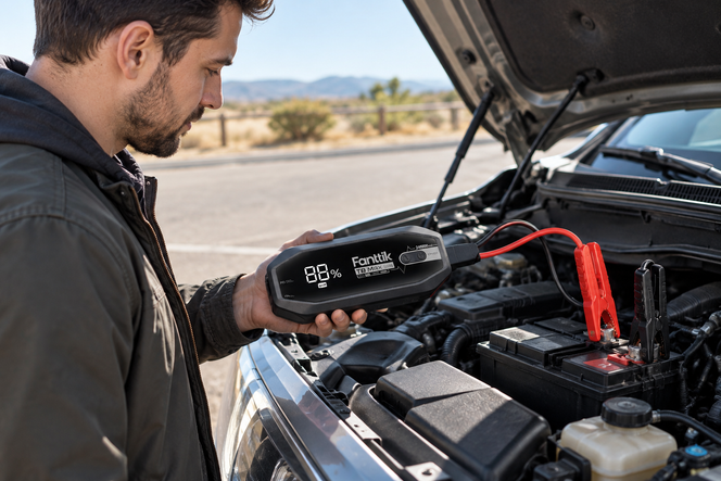 When a Jump Starter Beeps: Stop and Check Before Trying Again
A practical stop-and-check routine for a portable jump starter warning beep: record the details, find the exact model's...
 When to Finish Tiny Screws by Hand With a Precision Driver
Stop the electric driver at the screw's documented seat, add a hand turn only when the repair procedure...
Leave a comment
This site is protected by hCaptcha and the hCaptcha Privacy Policy and Terms of Service apply.