













Wiring an auxiliary light or dash cam reliably comes down to four linked steps: identify and isolate the circuit, mechanically lock the wires together before soldering, control the heat so the joint wets cleanly, and seal and support the splice so it can handle vibration and moisture. A soldered joint without that mechanical lock has nothing holding it together once the harness flexes, so solder alone is never the whole answer.
The sequence below walks through each stage in order, then splits into dash-cam and auxiliary-light specifics once the mechanics are covered.
What Is the Safest Wiring Sequence?
The safest path runs through seven stages in a fixed order, and jumping straight to soldering before the mechanical work is done is what leads to preventable rework later. Each stage has its own dedicated section further down.
- Identify the exact circuit, wire gauge, and accessory you're connecting.
- Disconnect and verify that the target wire is not energized.
- Plan fuse protection and the physical routing path before cutting anything.
- Build a mechanically secure Western Union or lineman splice.
- Solder the joint with controlled heat until it wets cleanly.
- Center and shrink adhesive-lined heat shrink over the finished joint.
- Test the circuit and confirm routing before closing up trim or loom.
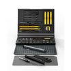
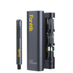
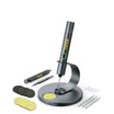
Before you start, gather a soldering iron kit, wire strippers, a multimeter, and adhesive-lined heat shrink sized for the harness. Working under the dash or under the hood also raises a power question worth settling early, since the corded vs cordless power decision affects how much working time and reach you get mid-splice.
What Must Be Verified Before Cutting Into the Vehicle Circuit?
Before any wire is cut, stripped, or heated, confirm three things: what the circuit actually is, whether it's currently energized, and whether it can be protected with an appropriate fuse. Skipping this check is how accessory splices end up on the wrong circuit.
- Trace the wire back to its source using the vehicle's wiring diagram or the accessory's own documentation rather than guessing from color or location.
- Confirm whether the path is an accessory circuit, a constant-power circuit, a ground, or something tied to restraint-system wiring.
- Disconnect the appropriate power source, then use a multimeter to verify the wire is not energized before cutting or heating it.
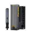
- Match your iron tip to the wire gauge; a set of replacement iron tips sized for smaller automotive conductors makes it easier to hold heat where you need it.
- Confirm you can add a documented, appropriately sized fuse to the power path before making the connection.
If removing trim exposes wiring that might belong to the airbag or restraint system, or if you can't positively identify the circuit, stop. Use vehicle-specific service information or a qualified installer instead of applying an ordinary accessory-splice method to wiring you can't confirm. Likewise, don't connect a power path you can't protect with a documented fuse.
How Do You Build a Western Union/Lineman Splice?
A Western Union or lineman splice is a mechanically interlocked wire-to-wire connection, not two conductors twisted together and coated in solder. The engineering standard covering this exact splice type describes a mechanically prepared Western Union/lineman splice that fully captures every strand and is protected against abrasion, vibration, chafing, and sharp edges, which is the same standard automotive splices should meet before solder ever touches the joint.
Strip and Align the Conductors
Strip only as much insulation as the splice needs, since exposed conductor that solder never reaches just becomes a weak point. Line up the two wires so the finished joint sits in a straight run rather than at a sharp bend, which makes it easier to cover and support afterward.
Wrap Each End Before Adding Solder
- Cross the two stripped conductors so each one has a straight length to wrap around the other.
- Wrap each end tightly around the opposite conductor, capturing every strand as you go.
- Check that no strand is left loose or sticking out before you apply any heat.
- If the wrap feels loose or twisted rather than interlocked, redo it. Solder is not a substitute for a poor mechanical connection.
Leave Room for Support and Sleeve Coverage
Keep the splice away from breakouts, sharp edges, and points where the harness flexes the most, when the routing allows it. Plan where the heat-shrink sleeve and any loom will sit before you solder, so the finished joint ends up supported rather than left hanging unsupported in the harness.
What Soldering-Iron Temperature Gives Clean Flow?
A practical starting point for many small-to-moderate automotive splices is roughly 660 to 750°F on the iron, adjusted from there based on how quickly the joint wets. That range comes from real-world automotive wiring practice rather than a formal standard, so treat it as a starting window, not a fixed setting.
Start With a Practical 660-750°F Range
Start near the lower end of that window if the joint is small and heats up quickly. Using a practical automotive starting range around 660 to 750°F reflects hands-on wiring guidance and works as a baseline rather than a rigid rule. Move toward the upper end only if a larger wire or connector is pulling heat away faster than the joint can absorb it.
Keep Three Temperatures Separate
- Solder melting range is a property of the solder alloy itself, listed on its packaging or datasheet.
- Iron working temperature is the setting you dial in on the tool.
- Heat actually delivered to the joint depends on tip contact, conductor mass, flux, and how long you hold the iron there.
Adjust From Solder Flow and Insulation Response
The target is a joint where solder flows and wets the strands cleanly while the insulation nearby stays intact. If the joint won't wet after a reasonable few seconds, or the insulation starts to soften, shrink, or discolor, stop and reassess your prep or materials rather than pushing the temperature higher.
How Do You Flow Solder Without Damaging the Harness?
Clean solder flow comes from heating the joint first, then feeding solder into the heat, not from piling solder onto the iron tip and hoping it transfers. This order keeps the joint from wicking solder too far under the insulation.

- Tin and clean the iron tip according to the tool and solder instructions before touching the joint.
- Heat the wrapped conductors directly, then feed solder into the heated joint so it flows through the captured strands.
- Stop feeding solder once it has wetted around the wrap; more solder past that point just stiffens extra wire and risks wicking under the insulation.
- Let the joint cool undisturbed. Moving it while the solder is still liquid can create a cold joint that looks solid but isn't.
- Inspect before covering it: full wetting on all strands, no loose strands, no sharp solder spikes, and insulation that's still intact.
If the joint refuses to wet after correct heat and clean prep, stop and check for contaminated surfaces or an incompatible solder alloy rather than holding the iron there longer.
How Should Marine Heat Shrink Be Positioned and Heated?
Adhesive-lined marine heat shrink protects the finished splice from moisture and abrasion, but only if it's sized, centered, and heated correctly. It doesn't replace the mechanical splice or the harness support that comes next.
Choose Tubing From the Finished Bundle
Size the tubing to the completed insulated bundle at the splice, not just the bare wire, since that's what it actually needs to shrink around. Installation guidance for adhesive-lined splice sealing calls for selecting tubing from the insulated bundle and confirming the strands are fully captured and the wire is free of oil, flux, and moisture before the sleeve goes on.
Center, Shrink, and Inspect the Sleeve
- Slide the tubing over the splice before soldering if the geometry requires it, then center it once the joint is done and cooled.
- Apply controlled, even heat from the middle of the sleeve outward, following the tubing's installation guidance rather than guessing at heat gun distance or dwell time.
- Inspect the cooled sleeve for full coverage, a conformed shape, visible adhesive flow at both ends, and insulation that shows no scorching or distortion.
Add Loom and Strain Relief Where the Location Demands It
Heat shrink seals the splice, but it doesn't carry mechanical load or protect against constant rubbing on its own. Where the joint sits near a moving part, an edge, or a high-flex zone, add loom, a clip, or a tie point so movement is absorbed by the harness rather than the splice itself.
How Do Dash Cam and Auxiliary-Light Circuits Differ?
A dash cam and a set of auxiliary lights both run on 12-volt vehicle power, but they raise different wiring questions and shouldn't share one wiring recipe. Knowing how to solder a car wiring harness for a dash cam accessory means paying attention to hardwire-kit behavior and interior routing, while auxiliary lights raise separate load, switching, and exposure questions.
Dash Cam Hardwire Planning
A dash cam's parking-mode and constant-power behavior depends on the specific hardwire kit and vehicle, so don't assume one kit's fuse-tap location or wake behavior applies to another setup. Route the cable through interior trim carefully, keeping clear of any wiring that might belong to the restraint system, and leave the connection accessible enough to service later.
Auxiliary-Light Planning
Size the power path, fuse, and any relay to the documented current draw of the specific lights you're installing rather than an assumed figure. Auxiliary lights are also more likely to sit somewhere exposed to under-hood heat, moisture, vibration, and road debris, so plan routing and sealing with that environment in mind, and keep the connection reachable for inspection or replacement.
Use the Accessory to Choose the Wiring Checks
| Factor | Dash Cam | Auxiliary Lights |
|---|---|---|
| Power behavior | Kit-dependent accessory or constant power, often with parking mode | Typically switched, sometimes relay-controlled |
| Fuse and current path | Sized to kit documentation, tapped at an accessible fuse point | Sized to the documented light load, dedicated fuse recommended |
| Ground and switching | Usually a simple interior ground | May need a dedicated switch or relay for higher current |
| Routing and exposure | Interior trim, away from SRS wiring | Often under-hood or exterior, more exposure to heat and moisture |
| Serviceability | Keep accessible near the mount for kit swaps | Keep accessible for bulb or fixture replacement |
Use the vehicle's own wiring diagram and the accessory's documentation to fill in exact fuse and wire-gauge values for either case; the table above is a planning frame, not a substitute for those numbers.
How Do You Test the Connection Before Reassembly?
A finished splice needs a visual check, an electrical check, and a function check before any trim or loom goes back on. Skipping straight to reassembly is how a marginal connection gets buried where it's hard to reach later.

Inspect the Cooled Splice and Routing
- Confirm full sleeve coverage with no gaps, scorching, or exposed conductor.
- Check that no loose strand or solder spike is pressing against the sleeve or nearby wiring.
- Flex the harness gently near the joint to confirm the splice isn't the only thing supporting it.
- Confirm the routed path clears heat sources, sharp edges, pedals, hinges, and other moving parts.
Check Polarity, Continuity, and Function
- Use a multimeter to confirm continuity through the splice and correct polarity at the accessory before applying power.
- Verify the fuse holds under normal operation rather than blowing immediately, which would point to a wiring or short-circuit issue.
- Power up the accessory and run it through its intended modes, such as parking mode on a dash cam or the actual switch position on auxiliary lights.
- Reassemble trim or loom only once every check above has passed; go back and correct any unresolved result first.
When Should You Stop and Get Qualified Help?
A handful of conditions make this job a poor fit for an ordinary accessory splice, and it's worth checking for them before you commit to a path. Each one below has a specific next action rather than a blanket warning.
- If you find wiring that might belong to the airbag or restraint system, stop. Preserve the harness and use vehicle-specific service information or a qualified installer instead of splicing into it.
- If you can't positively identify the circuit or its power source, stop and get documentation before cutting anything.
- If you can't establish appropriate fuse protection for the power path, don't connect the circuit until you can.
- If the existing insulation is brittle, melted, oil-soaked, or damaged beyond a clean local repair, replace that section of harness rather than splicing over the damage.
- If the splice location can't be supported or protected from heat, abrasion, or moisture, reroute it somewhere that can be, or use a different connection method for that spot.
FAQs
Can I use a Western Union splice for a branch connection?
A Western Union or lineman splice is built for one wire joining another in a straight inline run, not for a branch point with three or more conductors. If your layout needs a branch, a terminal junction, or a connection you'll need to service later, use a connector or harness method suited to that layout instead of forcing a wrap-and-solder splice where it can't be properly supported.
What should I do if the solder will not wet the automotive wire?
Stop adding heat and let the joint cool rather than holding the iron there longer, since prolonged heat won't fix a wetting problem. Check that the strands are clean, dry, and free of oil or old flux, and confirm you're using solder compatible with the wire. If the joint still won't wet after correcting those factors, redo the mechanical wrap rather than trying to force solder onto a contaminated or poorly prepared joint.
Should I seal a splice over brittle or heat-damaged insulation?
No. Brittle, cracked, melted, oil-soaked, or discolored insulation is a sign that the harness section itself needs attention, not just the splice. Identify the circuit, then repair or replace that section of harness using vehicle-appropriate wire and insulation before you build and seal a new splice there.
Continue reading
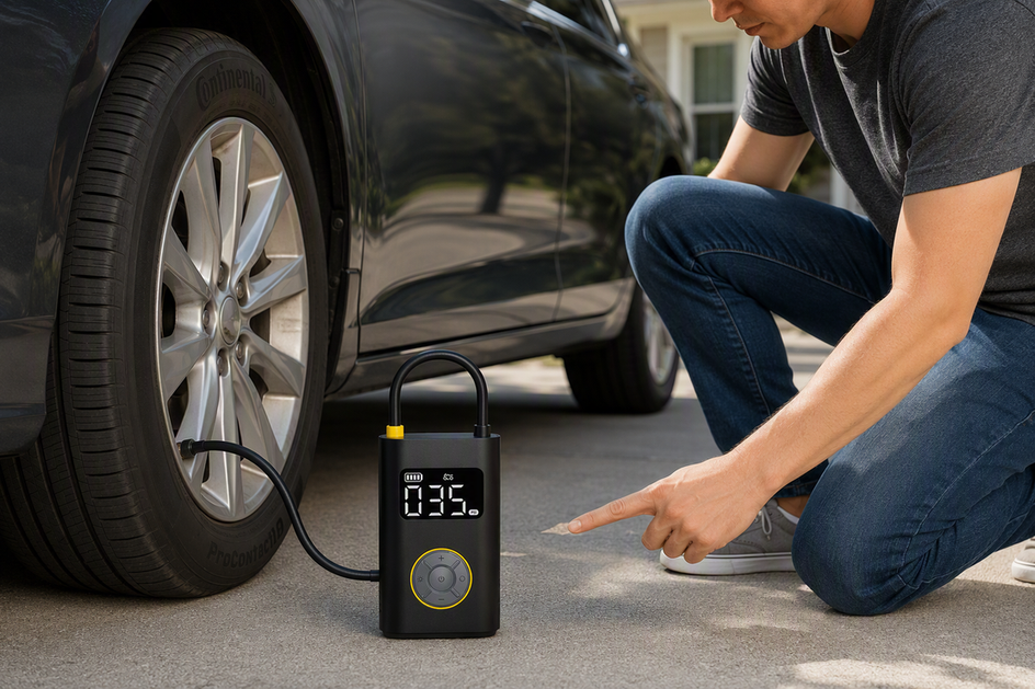 Cold Tire Pressure vs Hot Tire Pressure: When to Measure PSI Accurately
Cold PSI on the door placard sets your target. Driving raises tire pressure naturally, making proper measurement timing...
Cold Tire Pressure vs Hot Tire Pressure: When to Measure PSI Accurately
Cold PSI on the door placard sets your target. Driving raises tire pressure naturally, making proper measurement timing...
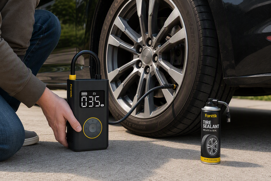 Why You Should Never Use Tire Sealant Cans as a Permanent Flat Repair
Aerosol sealant masks a leak but never replaces inspection. Here's what it can do to TPMS sensors, shop...
Why You Should Never Use Tire Sealant Cans as a Permanent Flat Repair
Aerosol sealant masks a leak but never replaces inspection. Here's what it can do to TPMS sensors, shop...

Leave a comment
This site is protected by hCaptcha and the hCaptcha Privacy Policy and Terms of Service apply.