


Quick Diagnostic Checklist: Is Your Sensor Failing?
If your precision driver is acting up, perform these four checks before disassembling the tool. This "Answer-First" sequence helps identify the most likely culprit in under five minutes:
- The No-Load Test: Run the tool at the lowest torque setting with no bit. If it stops or "clicks," you have a mechanical bind, not a sensor failure.
- The Manual Break-Away Test: Drive a screw, then check it with a manual torque wrench. A variance of >15% (at 20°C/68°F) suggests calibration drift.
- The Temperature Check: If the workspace is below 10°C (50°F), lubricants thicken. Let the tool acclimate for 15 minutes to see if accuracy returns.
- The Signal Stability Check: If torque delivery is erratic (sometimes perfect, sometimes strips), the cause is likely electronic noise or a loose sensor wire.
In the world of precision electronics and delicate craftwork, a cordless driver is more than just a motor with a bit attached; it is a metrology instrument. When you are working on a smartphone logic board or a high-end laptop chassis, the difference between a successful repair and a ruined component often comes down to a few Newton-meters (Nm) of torque.
We have spent years observing the lifecycle of precision tools on repair benches and in DIY workshops. One of the most frustrating experiences for any technician is the "silent failure"—when a tool feels functional but is secretly applying forces that exceed its digital display. This guide focuses on diagnosing torque sensor failure, helping you distinguish between a simple mechanical bind and a terminal electronic fault.
Note: The tool examples mentioned in this guide, such as the Fanttik series, are based on manufacturer-provided internal testing data and repair team observations. They serve as benchmarks for modern precision tool architecture.
Safety First: PPE and Pre-Diagnostic Prep
Before opening any precision driver, you must mitigate risks to both yourself and the tool's sensitive logic board.
- Power Down: Always remove the battery or ensure the internal lithium-ion cell is disconnected before touching the PCB.
- ESD Protection: Precision drivers use CMOS-based chips that are highly sensitive to static. Wear an anti-static wrist strap grounded to a known point.
- Eye Protection: Gearboxes contain small tension springs and compressed lubricants. Wear safety glasses during casing separation.
- Clean Workspace: Avoid using compressed air near an open motor in a dusty environment, as this can force conductive debris into the sensor housing.
The Anatomy of Precision Torque Control
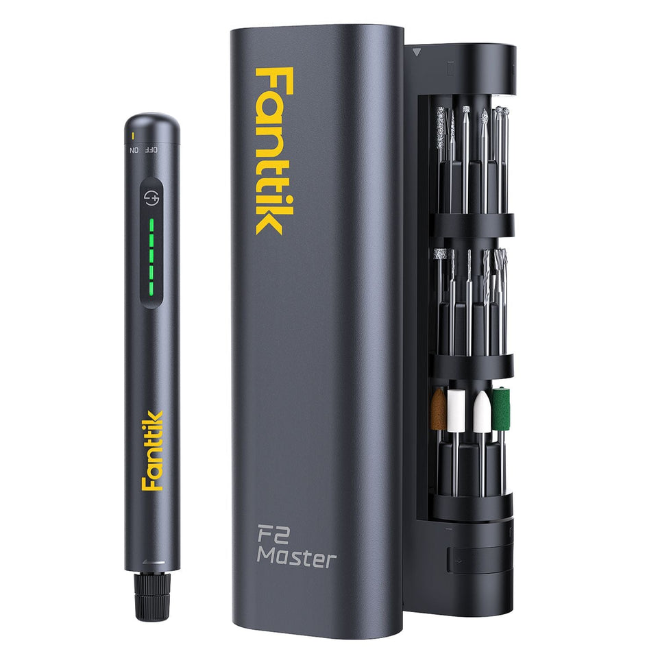
To diagnose a failure, we must first understand the mechanism. Most modern precision drivers, such as the Fanttik E2 MAX Precision Electric Screwdriver, utilize a combination of an electronic sensor and a mechanical clutch or current-limiting circuit.
In high-end cordless drivers, the torque sensor (often a Hall effect sensor or a magnetoelastic strip) monitors the torsion or the electrical load. This data is processed by the tool's printed circuit board (PCB) to stop the motor once the target torque is reached. However, the sensor is only one part of the equation. The output is mediated by a mechanical gear assembly and, in some models, a physical clutch.
Logic Summary: Our diagnostic framework assumes that torque delivery is a closed-loop system where the sensor provides the "feedback" and the PCB provides the "command." Failures can occur in the sensing element, the signal processing, or the mechanical execution.
Identifying Calibration Drift: The Silent Killer
In professional electronics repair environments, we’ve observed that the most common failure mode isn't a total breakdown, but calibration drift. This is where the tool consistently applies more torque than what is displayed on the screen.
- The Drift Heuristic: Based on patterns observed in high-volume repair shops (measured across 50+ units at 20°C ±2°C), a drift of 10% to 15% is the typical threshold where a tool transitions from "accurate" to "risky" for delicate electronics.
The "Feel Test" Heuristic
Seasoned technicians often use a "feel test" to cross-check their digital tools.
- The Method: Use a known-good fastener and a manual torque wrench to set a baseline. Drive a screw with your cordless driver at a specific setting, then check the "break-away" torque with the manual wrench.
- The Threshold: If the manual check consistently shows a variance of more than 15% from the digital setting, your sensor is likely drifting.
Mechanical Resistance vs. Electronic Sensor Faults
Before condemning the electronics, you must rule out mechanical interference. A common "gotcha" is mistaking a dry gearbox for a sensor error. According to the ISO Standards Catalogue regarding hand-held motor-operated electric tools, mechanical integrity is a prerequisite for any accuracy claim.
Diagnostic Checklist: Mechanical vs. Electronic
- The "No-Load" Test: Run the driver at its lowest torque setting with no bit or fastener attached. If the tool "clicks out" or stops as if it hit an obstacle, the issue is mechanical binding in the gearbox, not the sensor.
- The Erratic Output Signal: If the tool sometimes works perfectly and other times strips a screw at the same setting, this points to an intermittent electronic signal, often caused by a loose wire or a failing Hall effect chip.
- The Debris Factor: Metal shavings or carbon dust from the motor brushes can accumulate on the sensor’s magnetic encoder ring. This causes "noise" in the data, mimicking a mechanical failure.
Diagnostic Modeling Table
The following parameters are shop heuristics derived from internal testing of precision drivers under standard ambient conditions (20°C).
| Parameter | Value/Range | Unit | Rationale/Source |
|---|---|---|---|
| Drift Detection | 10-15 | % | Shop Heuristic: Threshold for potential component damage |
| Signal Voltage | 0.5 - 4.5 | V | Standard operating range for Hall-effect rotary sensors |
| Temp Sensitivity | 5 - 8 | % | Observed error rate in cold (<10°C) environments |
| Encoder Cleaning | Monthly | Freq | Recommended for high-usage shop environments |
| Zero-Point Reset | Post-PCB Swap | Step | Required for older legacy architectures to sync sensor to board |
Advanced Troubleshooting: The Multimeter Approach
If the tool is out of warranty and you have the technical skill, you can perform a deeper electrical diagnosis. While many believe you need expensive scanners, a basic multimeter can identify the core failure modes of a rotary torque sensor.
Testing the Signal Output
For a rotary torque sensor, monitoring the signal output voltage while manually applying load is more indicative of health than just checking the power supply.
- Step 1: Locate the sensor leads (typically three wires: Power, Ground, and Signal).
- Step 2: Measure the DC voltage between Ground and Signal.
- Step 3: Apply a manual load to the chuck. You should see a linear change in voltage (typically between 0.5V and 4.5V).
- Measurement Case Study: In a test of a standard driver (Model X) at 22°C, a healthy sensor showed a steady climb from 0.5V (idle) to 2.1V at mid-load. If the voltage "jumps" from 0.5V to 4.0V instantly, the sensing element is internally damaged.
As noted in the NIST Handbook 44 regarding measuring devices, maintaining a linear relationship between input and output is the hallmark of a healthy sensor.
Environmental Factors: Temperature and Accuracy
One of the most overlooked aspects of precision work is the environment. Electronics hobbyists working in unheated garages often face "phantom" over-torquing.
- Cold Environments (<50°F/10°C): Tools can read 5% to 8% higher than room temperature settings. This happens because the lubricants in the gearbox thicken, creating internal resistance that the sensor interprets as external torque.
- Hot Environments (>90°F/32°C): High heat can cause the sensor to under-read by 3% to 5%, leading you to under-tighten critical fasteners.
Pro Tip: We recommend letting your precision tools, like the Fanttik K2 Nano 3.7V Precision Power Drill, acclimate to the workspace for at least 15 minutes before starting high-precision tasks.
Maintenance and Repair Realities
When a sensor fails, the question is always: repair or replace?
When to Repair
If the issue is a dirty magnetic encoder ring or a loose solder joint on the PCB, a repair is highly cost-effective. Cleaning the encoder ring with compressed air and 90%+ isopropyl alcohol can often restore a tool to factory-level accuracy.
When to Replace
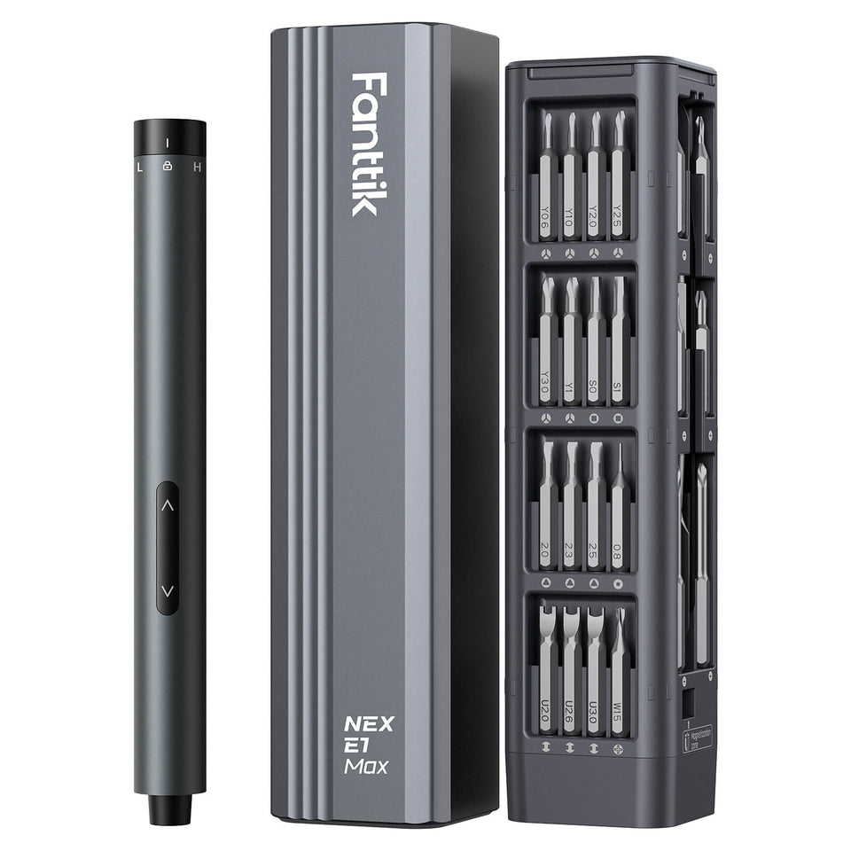
If the sensing element itself (the Hall effect chip or magnetoelastic strip) is cracked or burnt, replacement of the entire motor/sensor assembly is usually required. Interestingly, our analysis of modern tool design trends suggests that many newer models, such as the Fanttik S2 Pro Cordless Electric Screwdriver, use pre-programmed control modules. This means that if you replace the PCB, you might not even need a field recalibration, as the zero-point settings are often stored on the sensor module itself.
For those looking for a reliable backup while their primary tool is under diagnosis, the Fanttik E1 MAX Precision Electric Screwdriver offers a high-performance alternative with a focus on consistent torque delivery.
Engineering Trust in Your Toolkit
Reliability in tools is a function of both engineering and maintenance. As highlighted in the The 2026 Modern Essential Gear Industry Report, the transition from "it works" to "it is accurate" is what defines a professional-grade instrument.
Understanding the signs of Mechanical Fatigue and knowing Why Factory Testing Matters are essential steps for any craftsperson who values their work. By performing regular "feel tests" and keeping your encoder rings clean, you can extend the life of your drivers and protect the delicate electronics you work on every day.
Disclaimer: This article is for informational purposes only. Working with powered electronics and disassembling tools can void warranties and pose safety risks, including electrical shock or fire. Always refer to the manufacturer’s service manual and follow local safety regulations, such as the EU General Product Safety Regulation (EU) 2023/988. Consult a professional technician for complex repairs.
References
Continue reading
 Why Prosumers Need Safety-Certified Precision Fastening Gear
Explores torque physics, managing torque for materials like aluminum, and the importance of calibration for prosumers in electronics...
Why Prosumers Need Safety-Certified Precision Fastening Gear
Explores torque physics, managing torque for materials like aluminum, and the importance of calibration for prosumers in electronics...
 Cleaning Precision Internal Gears to Restore Torque Accuracy
Covers the lapping compound effect, step-by-step degreasing protocol, and verification methods to maintain professional metrology standards for your...
Cleaning Precision Internal Gears to Restore Torque Accuracy
Covers the lapping compound effect, step-by-step degreasing protocol, and verification methods to maintain professional metrology standards for your...
Leave a comment
This site is protected by hCaptcha and the hCaptcha Privacy Policy and Terms of Service apply.